This is version 2.5 of the manual for WorldEditor. To use this manual, you can jump to a section by clicking its title in the table of contents on the side. Clicking on terms highlighted in blue like this will take you directly to the relevant text or section. To search for a specific term or set of words, press “ctrl” (“command” on a Mac) + “f” to type the term and be taken to it anywhere in the document. For a PDF version of this manual, use an HTML to PDF converter such as pdfcrowd.com.
Scenery in the X‑Plane simulator can include essentially everything outside the aircraft. X‑Plane is designed specifically to enable users to create and modify scenery themselves. This means that, with a little ambition, a home user with no programming experience could design, say, a realistic version of their home town. This model of My Town, USA could then be easily incorporated into the X‑Plane simulator so that upon flying from Neighboring Town, USA into My Town, the scenery seamlessly and transparently moves into the super realistic scenery. These scenery packages can be even be distributed on the Internet so that anyone using the X‑Plane desktop simulator can download and install them.
Scenery in the X‑Plane desktop simulator is made up of both scenery files (apt.dat and DSF files) and “resources”, text files that describe the various entities referenced in the scenery package. This includes object files for describing buildings, network files for describing road patterns, forest files for describing vegetation, and so on.
In our scenery system, the world is divided into 1 degree latitude by 1 degree longitude tiles, each one of which is defined by one file. Custom scenery is stored in packages, or folders which contain all relevant files. Objects (in the form of OBJ files) can be placed at any location. These objects are most commonly buildings, but they could be houses, airplanes, or even people—X-Plane doesn’t know the difference. In addition to these custom objects, custom terrain textures may be used to create orthophoto-style scenery.
The X‑Plane scenery development kit contains the following:
The new scenery generation tools make extensive use of open source libraries; in order to comply with those licenses and to give back to the open source communities that make the new scenery possible, all of the new scenery tools have been released in source code as well as binaries. If you are a programmer interested in working with the scenery, we recommend working within the source code bases for these tools, as they already solve a number of problems relating to in-memory storage and processing of the new scenery.
X-Plane.org has web-based forums, including a forum dedicated to scenery creation. Additional guides, tutorials, tips and tricks can also be found on the X-Plane Developer site, including a 13 part video tutorial on airport creation.
To file any reports of bugs or problems with WorldEditor (or any of the other scenery tools), visit the scenery tools bug base.
The X‑Plane 8/9/10/11 scenery file formats differ from the old X‑Plane 7 formats in that they are open-ended; they can represent almost any configuration of scenery as long as a tool can create it. With X‑Plane 7, to implement new features with the scenery, the format had to change. Since X‑Plane 8, the format can represent almost anything. This means that the format will not change as we develop new scenery technology, all newer versions of X-plane can read older format files, and many existing sceneries can still be used in newer X-plane versions. Also, third party programmers will be able to design new scenery creation tools without being limited by our file formats, and it may even be possible to convert scenery from other flight simulators.
WorldEditor (or WED) is the scenery creation and editing tool for the X‑Plane flight simulator. It is designed to be a graphical tool for editing scenery overlays. It is able to:
WED is not used to edit base terrain meshes. Although these files also share the suffix .dsf , these files are different in that they give shape to terrain in X‑Plane. To create these files, use MeshTool, a command-line tool to build base meshes from raw data. WED is also not used to edit or create 3-D models of aircraft, buildings, or other objects in the world. For information on using 3-D modeling programs such as AC3D or Blender to create X‑Plane objects, see the X-Plane Developer site, or download the Plane Maker manual.
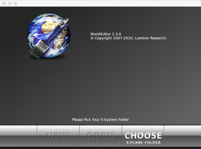
To use WorldEditor, do the following:
Figure 1: A first launch of WorldEditor, with all options disabled except for "Choose X‑Plane Folder"
WED will verify the selected folder as a valid X‑Plane installation by testing for the presence of the “Resources/default scenery/” and “Custom Scenery/” folders inside that location. After that the remaining “New” and “Open” buttons will be enabled, and WED is ready to be used.
X-Plane scenery comes in “packs.” A scenery pack is simply a self-contained folder with all elements of a scenery. These can include:
For more information on the contents of a scenery package, see the appendix Anatomy of the X‑Plane Scenery System.
WorldEditor creates its own file, called earth.wed.xml , in the folder that represents your scenery pack. All of your work in WED is saved in this file. You then “export” your work, which creates the final scenery in a format usable by X‑Plane. This workflow is quite similar to creating on a multi-layer Photoshop document, then saving a copy as a PNG for use outside Photoshop (emailing, posting to a website, etc.). Just like in Photoshop, the format used for editing a scenery file includes more information (and takes up more space) than the format used as output for an end-user.
WED’s own files have the advantage of letting WED save scenery information that isn’t normally present in a scenery package: hierarchy information, object names, and window positions. However, it has a few major impacts on your work:
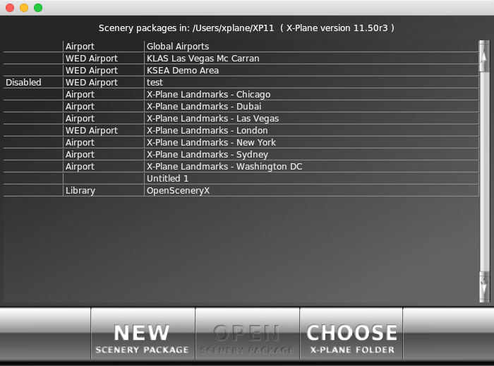
Figure 2: The scenery package list, visible when launching WED
By clicking any row from the table visible in Figure 2, then clicking the Open Scenery Package button, you can open an existing scenery package. Alternatively, you can use the New Scenery Package button to create a new, empty custom scenery pack.
The first column of the table can indicate a library or scenery that is disabled in the scenery_packs.ini configuration file. X‑Plane will not display such sceneries, but WED will still allow these to be edited. Disabled libraries will not be used by neither X‑Plane nor WED.
The second column shows some information about the contents of each scenery:
The third column is the name of the folder that holds the scenery pack or library. The name has no relevance to X‑Plane or WED and can be changed any time without affecting the scenery packs functionality.
Note that WED does not support windows shortcuts. Scenery packs not actually present in the ‘Custom Scenery’ folder must be referred to by symbolic links instead to be visible and useable in WED. See also the Windows blog or Howto Geek how to create symbolic links in windows.
The line at the very top of Figure 2 shows the X‑Plane folder last selected by the Choose X‑Plane Folder button as well as the version information from the last time X‑Plane was run in that folder.
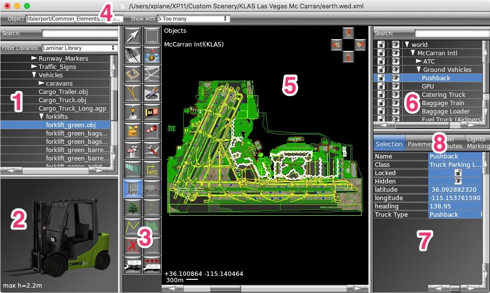
Figure 3: A typical WorldEditor window, click on the image for more information
All panes are user adjustable in size by dragging the dividers in between them. You can reset all panes to a usefull size very similar to Figure 3 by clicking on "Restore Frames in the View menu.
Additionally the left side panes (labeled 1+2 in Figure 3) and right side panes (labeled 6–8 in Figure 3) can be made to automatically open and close by moving the mouse to the side of the WED Window:
If you set either pane vertical divider so the side panes are fairly narrow (less than 100 pixels wide), but not completely closed - move the mouse over that narrow area and the corresponding side pane will expand automatically to a preset, usefull size. Move the mouse back over the center panes (labeled 3–5 in Figure 3) and the side pane will return immediately to its narrow size.
The map pane, numbered 5 in Figure 3 above, takes up the largest portion of the window by default. This is the pane that gives a top-down view of the scenery package as it stands. By mousing over the map pane and scrolling with your mouse, you can zoom in or out (note that the zoom will center around wherever your mouse is located—if you place it in the bottom right and scroll up, you will zoom in toward the bottom right of the window).
You can pan around in the map pane around by dragging it with the mouse while holding down the right mouse key.
If you ever lose your place in this view, you can click View from the menu and select Zoom World (to zoom out to where you can see the whole planet) or Zoom Package (to fit the view to the scenery package itself).
In this pane, you can visually add, move, and remove elements from the scenery package. The effect of clicking on an element in the map pane depends on what tool is selected in the toolbar.
In the right top corner of the map pane is a set of buttons to “tilt” the map pane, i.e. show the 3D elements viewed from an oblique angle. This is also known as a “birds eye view” and it allows to see the vertical walls of buildings and get a sense of the height of items.
The toolbar, numbered 3 in Figure 3 above and seen in Figure 4 below to the right, selects the “tool” currently in use. Different tools are able to modify different types of things in the map pane. These are as follows:
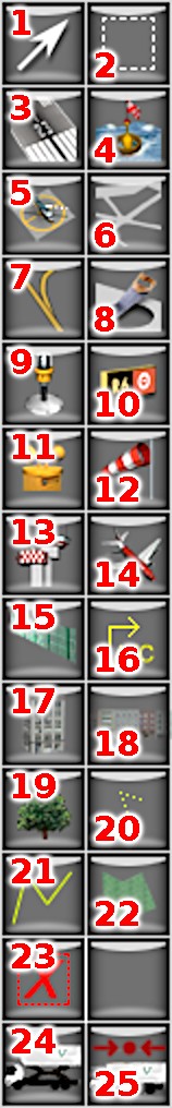
Figure 4: The tools in the toolbar, numbered in correspondance with the list to the left
For more detail on the tools described above, see the chapter Editing Using the Map Tools.
Numbered 4 in Figure 3, the tool defaults pane changes the settings for the currently selected tool. The available settings vary by the tool. For instance, the vertex tool’s only option is whether or not to snap to vertices (that is, to “jump” to existing points when dragging some vertex). The runway tool, on the other hand, can specify the runway’s surface and shoulder material (concrete, grass, snow, etc.), the roughness of the runway, the presence of centerline lights, and so on. For many tools, you can change the default resource by selecting that tool, then clicking an asset in the library pane (described below) that is usable by that tool.
Before using any tool, set up the preferences first and you won’t have to edit later. When you change the defaults for a tool, WED will remember those changes so that the next time you use the tool, it will be set up the same way. This saves time when drawing many similar types of things.
The library pane, numbered 1 in Figure 3, displays art assets currently available for inclusion in the scenery. Here, you can browse through the files in the X‑Plane library using their virtual paths. (For our purposes, a full understanding of the library system is not required, but for further reading, see the appendix About the X‑Plane Library System.) Selecting an asset will also select an appropriate tool—for instance, if you select a .obj file, the object tool will become active, and if you select a .for file, the forest tool will become active.
If you are looking for a specific asset, you can search the library using the “Filter” & “Choose Pack” boxes at the top of the pane. Click the “Choose Pack” box to display a drop down list of available library packs, and select the pack you’d like to search within. Next, type a search term in the “filter” box to see all available objects within the pack that include that term. For instance, if you were looking for a specific ATC tower, you might type “control_tower,” with the “airport scenery” pack selected. The library pane would show the Classic_Tower_1 object, among others.
You may also search the library using the special search operators $ and ^ . $ is an end-of-line indicator, while ^ goes at the beginning of a search. For example, searching for “Yellow” in the hierarchy search pane would return results with that word anywhere in the name or attribute. Searching for “Yellow$” on the other hand would only match items ending in “Yellow,” while searching “ Yellow ” would match anything starting with “Yellow.”
The library preview pane, numbered 2 in Figure 3, shows an accurate, real-time preview of some (but not all) art assets. When you select a .pol file in the library pane, the pane will be filled with the texture defined by that polygon asset. When you select a ‘.lin’, ‘.for’, .obj or .agp file in the library pane, a 3-D preview of the object or scene will appear in the preview pane. By clicking and dragging this preview, you can change your perspective, and you can zoom in using the scroll wheel on your mouse.
Rotate the preview object to see all wall types available for the facade. This works even if there are more than 4 wall types-just keep spinning ! Facades also can change in appearance depending on the height and width of any given wall. Drag the mouse holding the right button (as opposed to the left button, which is used to rotate the object) to change the height and width of the preview object and note the changes in appearance.
If there is more than one variant of the .fac file, you can also use the button in the preview pane to toggle through the options. Keep in mind that X‑Plane will select one at random every time scenery is loaded–there is no way to specify a variant the simulator should always use, so make sure your scenery design looks acceptable with any of these variants.
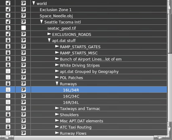
Figure 5: The hierarchy pane in WED
The hierarchy pane, numbered 6 in Figure 3 and shown enlarged in Figure 5, shows every element currently in the scenery package.
Using this pane, you can select an element or group by clicking on it. This will highlight that element in both the hierarchy and map panes. By double-clicking on an entity in the hierarchy, you can rename it.
By clicking and dragging an entity in this pane, you can change the order in which objects are drawn: objects and groups higher in the hierarchy will be drawn on top of those lower in the hierarchy whenever they overlap. For instance, in Figure 5, the “Runways” group is higher than the “Taxiways and Tarmac” group, so all elements within “Runways” will be drawn over elements contained in “Taxiways and Tarmac” if they happen to overlap.
To place one or more entities in a group, select them and press Ctrl+G on the keyboard (Command+G on Macs), or select Group from the Edit menu. To ungroup elements (that is, remove a group, leaving all entities the group previously contained at the same “level” as the group was), select a group label and press Ctrl+Shift+G (Command+Shift+G on Macs), or select Ungroup from the Edit menu.
By clicking the lock icon, you can lock an element or group to prevent further visual editing. Note that is applies only to editing within the map pane; changing the element’s properties in the editing tabs (beneath the hierarchy pane, described below is still possible. Note also that this property applies recursively: if a group in which an element resides is locked, that element will also be locked.
Next to the lock icon is an icon that looks like an eye. This toggles the visibility of an element or group. Invisible elements will not be exported for use in X-Plane, and will of course not be visible in the map pane.
To delete entities, select them in the hierarchy and press the Backspace or Delete key on the keyboard, or select Clear from the Edit menu.
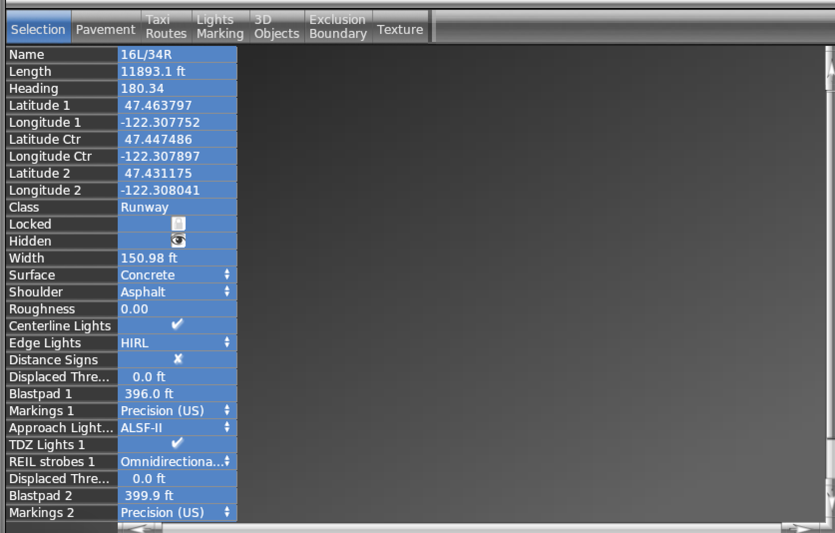
Figure 6: The editing tabs and attributes pane in WED
The attributes pane, numbered 7 in Figure 3 and seen in Figure 6, contains a number of editing tabs, which allow for editing of elements based on their type. The first tab, labeled Selection, shows in full detail whatever scenery element is currently selected. Because of this, it changes the properties displayed in order to match the currently selected element.
The tabs numbered 8 Figure 3 reduce clutter by selectively limiting the visible entities in the map pane. They also lock the hidden objects so they cannot be moved on the map by mistake when in a tab mode.
The Selection tab makes all types of scenery items selectable and shows everything, except for some clearances around ATC routes and road networks.
The Pavement tab allows you to access only the underlying ground cover of the airport, with other details removed. Only runways, taxiways, draped polygons and orthophotos are unlocked and visible in this mode.
The Taxi Routes tab allows you to easily edit ATC operations at an airport. Only ramp starts and ATC taxi routes are unlocked, but most pavement, such as taxiways, runways, facades, and orthophotos are visible but locked from editing.
The Lights and Markings tab allows editing of non-sign details on top of base pavements. Line and string files, taxiway lines, light fixtures and windsocks are unlocked in this mode, with underlying pavement visible but locked.
The 3D Objects tab allows you to edit 3D clutter and buildings, such as facades, forests, and objects. Underlying pavement is visible but locked again in this mode.
The Exclusion and Boundary tab allows fine editing of exclusion zones and airport boundaries, with most airport features visible but locked in this mode.
The Texture tab is for texture mapping a custom draped polygon file named “Draped Orthophoto.” To add these to the scenery, select a .pol file in the library pane, then select Use Texture Map in the tool defaults pane. Some .pol art assets (such as the DrapedRunwaySigns.pol) come with special pre-defined “subtextures” that can be pre-selected by a mouse click on the relevant part of the texture in the library preview pane.
After drawing your shape with the polygon tool, use the bounding box in the texture tab to select what part of the original image is displayed in the shape. Use the Snap to Vertices options for the most precision. Note that this tab only works with custom draped polygons that have been drawn with the Texture Map box checked. Custom scenery that use custom textures or or .pol files other than those included in the Laminar Research default library are not eligible to upload to the Airport Scenery Gateway.
The taxi sign editor is “what you see is what you get” (WYSIWYG).
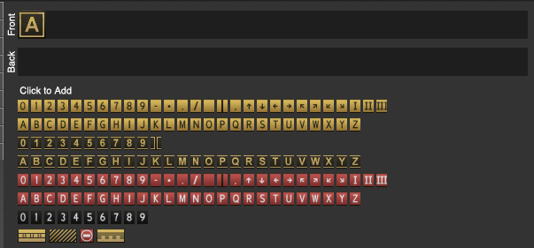
Signs in the hierarchy are shown as a rendered preview of what the sign will look like. When you click on the line, you open the editor with two “text” fields where signs can be directly typed, and a palette where signs can be added by clicking. If the raw definition code is showing, this indicates the taxi sign fails to meet the syntax rules as outlined on page 13 of the apt.dat specification. The fastest fix may be to clear the existing sign text completely and create new text with the WYSIWYG editor.
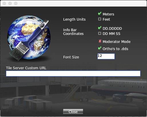
Figure 7: The options in the preferences window
WED has globalized preference settings that will apply to every scenery pack. This menu is found under File > Preferences (or WED > Preferences on Mac OS). Here you can change between meters and feet, or how the coordinates are displayed in the map (although you can only enter coordinates as decimals still). The size of all text in WED can be specified as well. Most tables and menus will adjust to this size instantly, but some may require a restart of WED for best appearance. See the section “Using Orthophotos for Scenery and Guides” for information on how to use the Tile Server Custom URL field.
This tutorial steps through the creation of an airport from scratch, including runways, taxiways, air traffic control frequencies, and more. It also discusses adding orthophotos and objects to the scenery. Finally, it details exporting the package for use in X-Plane.
Alternatively, see WorldEditor in action by watching the 13 WED tutorials on YouTube that show how to create a simple airport.
Note: Before beginning, make sure you are familiar with the basics of the WED interface, discussed in the section Using the WorldEditor Interface above.
If you have not installed WorldEditor yet, do so according to the section Downloading and Installing WorldEditor above.
To begin, we will create a new scenery package in WorldEditor. Launch WED and click the New Scenery Package button, as seen in the image below.
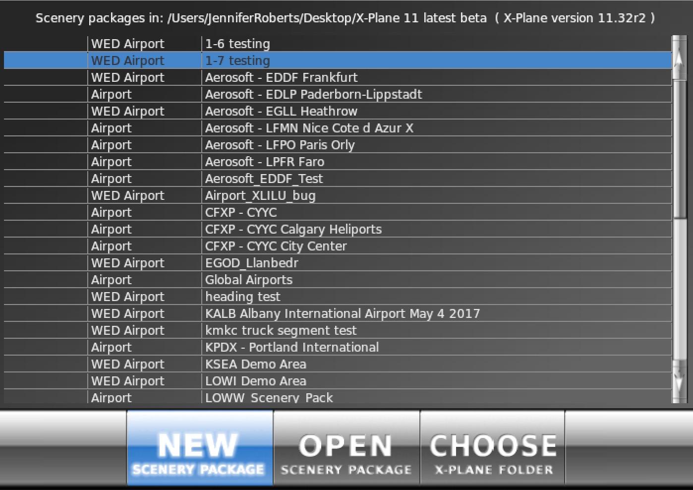
Figure 8: Clicking the New Scenery Package button from the WorldEditor launch window
Click on the new airport in the list and type a name for it (this name is unimportant except as an identifier for your own use). With the name entered, click the Open Scenery Package button. After a moment, the WED drafting window will appear, showing a new, empty scenery package.
Now is a good time to save your work, and to get into the habit of saving often!
We will now set up the airport that X‑Plane will use. A scenery package does not need to be associated with an airport, but it is generally the case that people create scenery packages around some airport.
You have two options regarding the airport data used in your package: you can either use a default airport (and modify it if necessary), or create a new one from scratch. The airport data included with X‑Plane by default is generally of high quality, even in cases where only the main runways are included, so it is most common to import the existing data.
Scenery artists can import airport data from the Airport Scenery Gateway database as well. First, select the option “Import from Airport Scenery Gateway” from within the File menu. The window that opens will download the airports currently available in the database, so you must be connected to the Internet to use the feature.
You can search by ICAO in the Filter field, or scroll through the list to see if any scenery for an airport exists. Click “ICAO” to sort the list by identifier or “Name” for alphabetical sort. Data in the “Checked Out Until” and “Artist” columns indicates other Gateway artists reporting via the Airport Scenery Gateway website that they are currently working on updates for that airport. Such tags will not affect the ability to down or even upload modified airports, but can be used to avoid duplicate efforts.
Highlight the airport line then click Next to see all of the submissions of that airport in the database. Notes are included for each submission letting you know what user submitted it, how old it is, its status (such as whether it’s the recommended version), and any comments included by the creator. Pick which version(s) you’d like to import and click the Import Pack(s) button.
Multiple submissions of the same airport can be imported at one time, however we suggest that you only import the version labeled “Recommended” to avoid confusion between packs, and to work with the most complete data for the airport. Alternately multiple airports can be highlighted in the initial selection list, in which case the recommended version for each airport is imported without further user input.
You can import airport data saved on your computer via the File menu > Import apt.dat. Navigate to the apt.dat file you wish to import from in the next window. Then WED will ask which airports within the file to actually import. Type the ICAO identifier of your airport in the text box labeled Filter (found at the top of the dialog box), click your airport to select it (or hold Control/Command and click multiple airports to select them all), and click Import. At this point, all existing data on your airport is present in your project.
In most scenery packs, additional 2-D and 3-D airport scenery is stored in DSF files, which have to be imported separately with the “Import DSF” function in the File menu. Note the DSF format is a lossy, compressed format (similar to .jpg images), so the precision is less than when importing from the Airport Scenery Gateway or using an earth.wed.xml file, if available. This imported DSF data will show up in a separate group named after the path of the DSF file imported. At this point it is not associated with any airport previously imported from the apt.dat file. This group must be dragged in the Hierarchy Pane into the hierarchy of the intended airport to restore all functionality of this scenery in X-Plane.
If you choose to create an airport from scratch rather than importing one from existing airport data, open the Airport menu and click Create Airport. A new group will appear in the hierarchy paned labeled “unnamed entity.” Click twice on this name in order to rename it to match your airport’s name.
With the newly created airport selected, we can enter some basic information about it in the editing pane (beneath the hierarchy pane). Using the Airnav database, you can find the airport’s elevation, ICAO identifier, and so on. (Note that, by default, the elevation is in feet above mean sea level. You can change these measurements to meters by changing your preferences.)
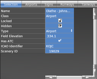
Figure 9: Setting the field elevation, ATC presence, and ICAO identifier for an example airport
Whether you are creating an airport from scratch or importing an existing one, there are some data fields that should be filled out for all airports, such as the name, type, elevation, ATC, and ICAO. The scenery ID field relates to Gateway imports and should usually be left alone.
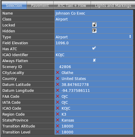
You can specify whether base mesh flattening will be applied to only this airport with the “Always Flatten” option. In addition, up to 11 “Meta Tags” can define many properties important for ATC and navigation functions associated with a given airport. These can be automatically filled in for new airports by choosing Update Metadata from the Airport menu. You can manually add metadata fields by choosing Add metadata then the appropriate option if the automatic update doesn’t return any results.
The most frequently edited meta tags are the “ICAO code,” “FAA code” and “Local Code” meta tags. The airport selection windows in X-Plane, all GPS and FMC navigation use these meta tags only to display the airport’s identifier. The “Airport ID” property in WED or as used on the Airport Scenery Gateway is no longer used to determine the airport identifier in the X‑Plane user interface and may therefore differ from the Airport ID. If an ICAO or otherwise locally issued identifier changes, the relevant meta tags are to be edited to reflect the new identifier, while the Airport ID in WED, on the Gateway and in all scenery files must never change once assigned.
An important concept in WED is the idea of the “current airport.” The current airport is the one named in the upper left of the map pane, as illustrated in Figure 10. If there are no airports in the scenery package, there is no current airport. The current airport is the airport with which all new scenery elements (runways, objects, etc.) will be associated by default. Thus, if you have 3 airports in your scenery package and you draw a new runway, that runway will appear within the hierarchy of your current airport. Note, however, that it is the hierarchy pane which ultimately determines what airport a scenery element will belong to. If you create an entity at the wrong airport, you can always drag it in the hierarchy pane so that it belongs to the right airport.
To switch between current airports, select the airport you would like to edit from the hierarchy pane, then select Edit Airport (airport name) from under the Airport drop down menu.
![The current airport listed in the upper left of the map pane][images/updates/current_airport.jpg]
Figure 10: The current airport listed in the upper left of the map pane (in this case, KOJC/Olathe-Johnson County Executive)
When drawing runways, adding lighting, and so on (all discussed in the rest of this chapter), it may be helpful to have a real-world photo to guide you. Since X‑Plane global scenery includes all roads, coastlines, and other data from OpenStreetMap data, WED can display these maps automatically by choosing View menu > Slippy Maps > OpenStreetMap. The maps are downloaded directly from the web, so this feature requires internet connectivity. Once loaded, the maps are cached on disk for at least one month to support continuing their use while offline.
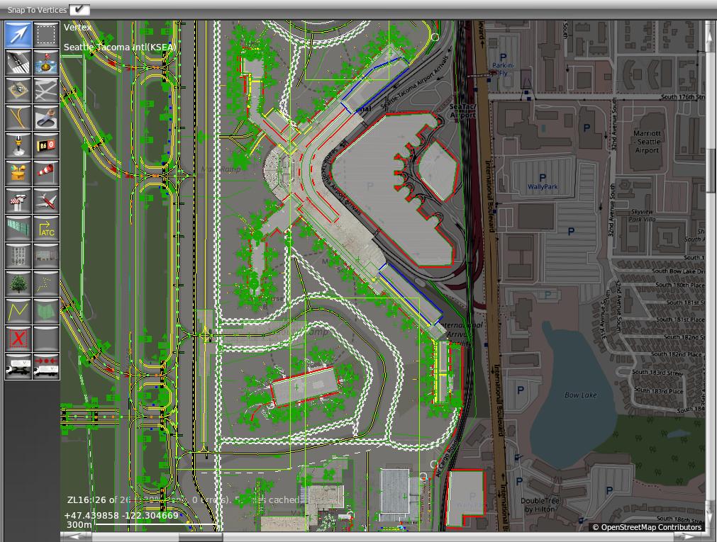
Figure 10: The OpenStreetMap data underlying the KSEA demo area
Another very popular option is to trace features from satellite imagery. This is supported by choosing View menu > Slippy Maps > ESRI Imagery. This imagery is also data is cached on disk and available for offline use the same way as the OpenStreetMap data.
If you would prefer to use slippy maps of your own choosing, enter the tile URL (using syntax as shown in this article) in the “Tile Server Custom URL” field in the Preferences window. Please note that using this feature will legally prevent sharing the scenery you create, under any circumstances. Use this feature at your own risk as many services (Google Maps for example) strictly prohibit using their data unless it is purchased from them.
A third option is to download or create with any suitable 3rd party application georeferenced images in the GeoTiff format. For these use View menu > Pick Overlay Image… to import. These images will be placed into the correct position automatically, but if for some reason the georeferencing data can not be read, the image is placed in order to completely and exactly fill the current map window in either width or height, preserving the image’s aspect ration. If this happens, the image corner coordinates can still be entered manually by selecting the reference image’s corner and entering the Longitude/Latitude properties for each.
All of the above methods are for images that are only visible in WED to assist with scenery creation and layout. If instead you want your images to be exported as part of the scenery pack, you would need to import orthophotos using the File menu > Import Orthophoto option. If you do not want to use orthophotos in your scenery, you can instead skip to the section “Adding and Modifying Runways or Sealanes” below.
Orthophotos are real-world aerial photographs which overlay the terrain in X-Plane, and are seen in scenery packages like those of RealScenery), and to use them you must first download some high quality orthophotos of the area.
For scenery in the US, it’s easy to obtain public domain orthophotos that may be used freely in our scenery; you can download them from the USGS Seamless Server. Outside the US, it may be more difficult—-copyrights on most imagery like this will prevent you from using or distributing the images with your scenery.
Note: When downloading orthoimagery other from any service other than the USGS, their individual copyrights must be respected. Therefore, it is recommended that only images from the USGS be used in WorldEditor. Additionally, scenery that uses orthophotos may not be uploaded to the Airport Scenery Gateway.
From here on, we will assume that you have either downloaded orthophotos from the Seamless server, or that you have similar files from some other resource. The advantage to using the Seamless server is that you can download image files that have their geographic coordinates embedded in the files themselves.
Be sure to put the orthophoto image files you downloaded in your custom scenery pack folder.
Adding orthophoto scenery is as simple as importing and, if no georeferencing information is included, positioning the image, customizing the rest of your airport’s features, and exporting the scenery pack. WorldEditor will automatically take care of any necessary image resizing and splitting large images into smaller textures without resolution loss, as well as the creation of image format and draped polygon files.
Supported image file types are: .bmp, .dds, .jpg, .png, and .tif. The recommended maximum image size is up to 16,384 pixels per side. Note that while WED can accept images of any size and shape, some resizing or transformation may occur if the source image is not already to the power of 2, or basically square.
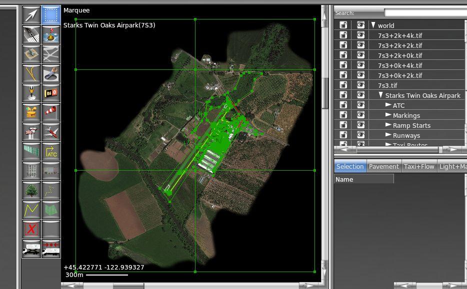
Figure 11: An orthophoto inserted into a WED project
To get started, open the File menu and select the Import Orthophoto option. Note that the image file must be located inside the scenery pack’s folder as all output files created by WED will be placed in the same location. Navigate to this folder and select the orthophoto files you downloaded previously. Assuming the coordinate information in the files is correct (and that the file type includes embedded coordinates), WED will automatically place the images where they should be.
Use the Marquee tool to select the newly inserted images, then give them a meaningful name in the hierarchy pane.
If your image did not include coordinate information, and you need to fine-tune the placement of your images, use the vertex tool to highlight the corners of you images. With a corner selected, you can use the Selection tab (in the bottom right of the window) to tune its latitude or longitude coordinates, along with its other properties. Alternatively, you could select your image’s corners and drag them to move them, holding the control key to preserve the aspect ratio if desired. This is, for obvious reasons, not nearly as accurate as putting in the exact coordinates that you want for the image.
With the image’s position perfected, you should be able to zoom in on your runways and see the X‑Plane runway aligned (nearly) perfectly with the runway in the photo.
You may want to group all your overlay orthophotos if you are using more than one. To do so, select them all by holding down the Ctrl key (Windows) or Command key (Mac) and clicking the orthophotos in turn. Open the Edit menu and click Group, or Ctrl or Command + G. Once they are grouped and in place, you can keep them from being accidentally moved by clicking the lock image next to them.
Finally, to make sure that your overlay images don’t hide other parts of the runway, select the group containing all overlay images, open the Edit menu again, and select Move Last.
WED will check the last modification date of the referenced image file every time the scenery pack is exported. If the original image is newer than the .dds created from it (e.g. because it was edited with an external photo editor), WED will re-create the .dds files as needed. If the corresponding .pol files are edited after initial creation by WED they will never be overwritten either, so as to preserve any manual edits applied to them.
To add a runway, simply select the runway tool (numbered 2 in Figure 4), then click twice in the map pane to visually set the two endpoints of the runway. For the sake of consistency, click first on the northern or western end (depending on the runway’s orientation) and clicking second on the southern or eastern end. Note that for now, this does not have to be very precise—we’ll clean it up momentarily to make it pin-point accurate. (Note that sealanes are added identically to runways, but they use the sealane tool rather than the runway tool.)
After your second mouse click, the green drawing line will turn into an orange outline, and the runway will appear in the object hierarchy pane, with a long list of attributes below it.
After having placed the runway roughly where it belongs, use the Airnav database or another reference to manually specify the exact endpoints of the runway, as well as its other properties. With the runway selected (either because you just drew it or because you used the marquee tool and clicked on it), click the Selection tab (found among the editing tabs, described above). You should begin by setting the “Latitude 1” and “Longitude 1” attributes—these are the coordinates of the first end you drew previously, which should have been the northern or western end of the runway. Then, input the “Latitude 2” and “Longitude 2” coordinates. (Note that the Latitude/Longitude Center, Heading, and Length attributes will all be calculated automatically from these.)
Beyond these attributes, the order in which you input the data does not matter. At the very least, you should specify the runway width, the surface, and, of course, the name. Be sure to enter the name as low/high numbers. For example, 18/36 is a legal name while 36/18 is not.
Note that, for all attributes with “1” and “2” variants, the “1” end is the end you clicked first when drawing.
Some important attributes whose significance may not be obvious are:
Having finished modifying a runway visually, you may want to lock it (as described in the section on The Hierarchy Pane above). Another good idea is to very its alignment with any existing X‑Plane NAVAIDs, such as ILS, VOR and NDB systems. This can be done by checking the Navaids option under the View menu to display all such installations as defined in the default NavData of the current X‑Plane install.
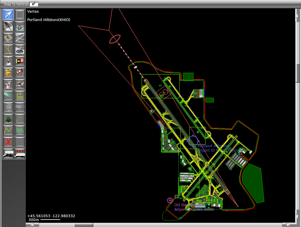
Figure 12: The NAVAID overlay showing ILS localizer, Glideslope and Inner Marker correctly aligned with runway
Note this NAVAID layer is read-only–in other words it cannot be edited in WED. To request a fix to any discrepancies observed, file a bug report in the “NAVAIDs” tab on the Airport Scenery Gateway “Report a Problem” page.
If a runway has been modeled using an OBJ or some other specific technique that replaces X-Plane’s runway, a transparent surface can be selected from the drop down menu in the editing pane. This will allow users to get all of the menu items and approach lighting associated with a real runway, while still being able to set the surface physics and graphics themselves (using a draped polygon, with its physics specified in its .pol file). This is an advanced scenery design technique and not allowed on airports submitted to the Airport Scenery Gateway.
The taxiway tool is used to draw taxiways and other pavement (including aprons, parking lots, and so on) using Bezier polygons. Taxiways are much more than just “colored areas” in the scenery–they also create smooth surfaces, are shown in the Airport diagram of the X‑Plane map, affect how runway lights are shown, and more. They are functional elements of the airport and should not be used for anything but surfaces where aircraft do actually taxi. They are not to be used for roads, building footprints or other paved, grey surfaces–use polygon (.pol) files for these features.
Before beginning, it is important to ensure that, when drawing these polygons, there is only one enclosed area per polygon—that is, make sure that the outline does not cross over itself at any point. To ensure the taxiway aligns correctly with the runway or other pavement when rendered in X-Plane, be sure the two surfaces overlap a bit or that the points snap together. (See the Taxiway Shapes article for more information.)
With this in mind, select the taxiway tool from the toolbar and create a rough outline of a section of pavement. At this point, you should not be making the shapes especially detailed—use a small number of nodes, with the intention of cleaning the shape up later. Finish the shape by hitting the “Enter” key or clicking on the first node you placed, which will have a circle around it. If at any point you need to delete/remove a single vertex, you can use the vertex tool to select that vertex and hit the delete key. The vertex will be deleted and a straight line will be drawn between the two remaining vertices on either side of the deleted vertex.
Perhaps the easiest way to handle the airport’s taxiways is to outline all the taxiways and other pavement in your object, then use the hole tool to cut out all the area that was selected which isn’t pavement. If you are using an orthophoto, it will be helpful to change the transparency of the taxiway in order to see where the holes should be drawn. To do this, click the View menu and select “Pavement Transparency.” Set the taxiways to 50% transparency for a good balance.
For instance, on the left in Figure 13, the taxiway has just been drawn—it covers a lot of area that it shouldn’t. Then, on the right, holes have been cut in it so that it doesn’t cover the grassy areas around it. It still isn’t pretty, but we’ll clean it up soon to more closely match the real taxiways.
For information on how to use the hole tool, see the section “Cutting Holes in Bezier Shapes.”
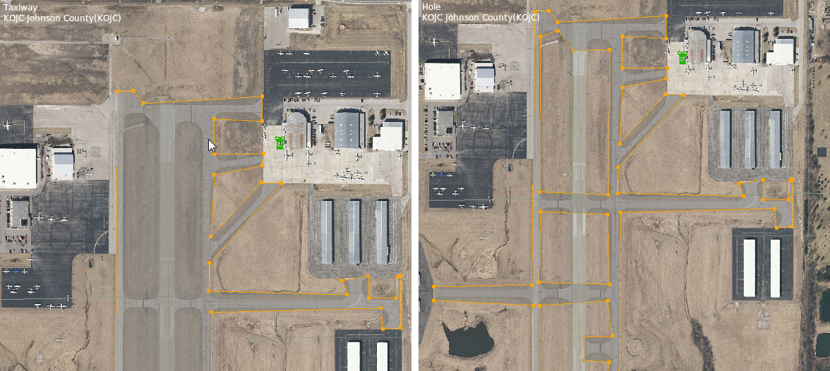
Figure 13: The rough outlined taxiways, before and after cutting holes in them (left and right, respectively)
Drawing one large taxiway and cutting holes will not work if you need markings on your (true) taxiways, though—in that case, you’ll need separate entities for each taxiway.
Now that we have a very basic outline of our pavement drawn, we need to modify it to follow the contours of the actual airport’s curves. We’ll do this by turning the node near a corner into a curving node in the Bezier path, which will cause the line connected to it to curve around it. To convert a plain node to a curving one, hold down the Alt key and drag the mouse away from the point. After you let go of both the mouse and the Alt key, you can click and drag the outside arrows to further tune the curve.
You may need place an extra node between two points for the purpose of creating this curving node. To split the line connecting two points and place a node between them, highlight the points using the vertex or marquee tool, open the Edit menu, and click Split. Alternatively, you can highlight the points and press Ctrl+E in Windows, or Command+E on a Mac.
Repeat this process for each curve around the pavement.
For information on switching between the different types of nodes, see the chapter Bezier Path Tools.
Now we will add markings to our runways, taxiways, and other pavement. Markings come in two varieties: perimeter markings (found around the outline of taxiways), and overlay markings (like taxilines, ILS, and hold short markings). The latter are essentially stand-alone lines, so they may also be useful for coping with complicated taxiway layouts
Note that whenever you select a tool that supports markings (e.g., the taxiway and taxiline tools), you can set that tool’s default markings (using the tool defaults bar at the top of the window). When you select a default marking in this pull-down menu, that marking will be applied to that tool until you change it. So if you were going to draw taxilines, you would select the taxiline tool, set the Markings drop-down to “Double Solid Yellow (Black),” then begin drawing the shape.
You can, however, draw the shape first and add the markings later. This is easily accomplished by selecting an entity (like a taxiway) with either the vertex tool or the marquee tool, then going to the attributes pane and setting the Line Attributes, Light Attributes, or both, under the Selection tab. When you do this, the markings will be applied to the entire shape. This is generally not what is desired, though, and you’ll need to remove the markings from some of the segments for taxiway intersections and the like.
To remove the markings from one section of the taxiway, select a single node using the vertex tool. Then, in the attributes pane Selection tab, set its Line Attributes to none. The line connecting this node to whichever node was drawn after it will no longer have that attribute. For instance, if you selected Node 9 and set its Line Attributes to none, the line connecting it to Node 10 would have no markings.
Adding ramp starts via the the ramp start tool will create the list of ramp starts seen in the Global Airports screen of X‑Plane. These are places you can start your flight from, where parked aircraft are drawn, or AI aircraft may taxi to and from during their operations.
Select your ramp start type: gate, tie down, or hangar. You can only have one of these checked at a time, but all types are displayed in the Ramp Start list of the Airport Map in X‑Plane. AI aircraft can use the gate and tie down types only, and push back services are only available at gate type ramp starts. Misc (checked by default) and hangar types are only usable by the sim pilot.
The equipment type field tells X‑Plane what type of aircraft would use this ramp in the real world. This is mostly used for spawning the correct type of AI planes. Pick at least one type of plane from the list.
Specifying the size, operation type, and airline fields will help X‑Plane populate airports with the most accurate mix of AI aircraft and static objects. Note that changing the Size field will change the size of the yellow icon. This is to help visualize how much space will be taken up by the largest aircraft of that category. Be sure to provide plenty of clearance–if any part of the icon is covered, there will not be enough space there in X‑Plane and taxiing aircraft will become stuck when trying to pass. Keep in mind that viewing the layout in the “Taxi+Flow” editing tab will make these issues easier to spot.
If you are importing an airport from an earlier version of WED, use the “Upgrade Ramps” option under the airport menu to automatically convert old style ramps to the new format compatible with X‑Plane 10.50.
A runway or taxi sign is simply a directional point entity, which means it is placed and rotated just like other directional point entities. To place a new sign, select the taxi sign tool from the toolbar, then click in the map pane wherever the sign should be located. The new sign is represented as a rectangular icon with an arrow emerging from one side to indicate its heading—the front of the sign is the side with the arrow emerging from it. Note that you can rotate the sign as you create it by clicking and dragging, or you can change its heading later using the vertex tool.
Once the sign is positioned, click on the line in the hierarchy to open the sign editor and change the Name parameter to specify what the sign actually says. You can type directly on the line or click on individual icons in the editor. With the sign editor, you cannot create an invalid sign–the editor knows the syntax rules. If you see pure text, the sign is already invalid and you will need to delete the offending part or redo it. (Use the Validate option to point out sign syntax errors.)
The sign specification used by X‑Plane is shared by the FAA, and it is largely in line with other aviation authorities worldwide. Scenery artists may find it helpful to review “ICAO Recommended Airport Signs, Runway and Taxiway Markings,” which outlines how real-world taxi signs are positioned and designed.
Windsocks, light fixtures, and airport beacons are all placed on the airport like runway signs (described above)—click to place them, and, in the case of the light fixtures, drag the cursor to change their orientation. You can use the marquee tool to change their position, and, in the case of light fixtures, you can use the vertex tool to change their heading.
To create a helipad, simply select the helipad tool, then click and drag in the map pane to both set the pad’s location and its heading. After placing a helipad, you can set the helipad’s name, surface type, marking type, size, and so on using the attributes pane (either the selection tab or the helipads tab, depending on your preferred workflow).
Airport boundaries define the edges of the area considered an airport. These are used primarily when new global terrain is generated—they enable our scenery generation algorithms to flatten the appropriate airport terrain, and to apply appropriate land use textures. The elevation of the airport area is pre-processed to remove bumps and radar spikes (flattened), and the terrain type is set to airport grass.
Guidelines for drawing the airport boundary:
Figure 14 shows a possible boundary for BWI. Note that the forest areas are probably on the property of the airport legally, but are not part of the airport boundary in the diagram so that the trees are not replaced with grass when the airport is built.
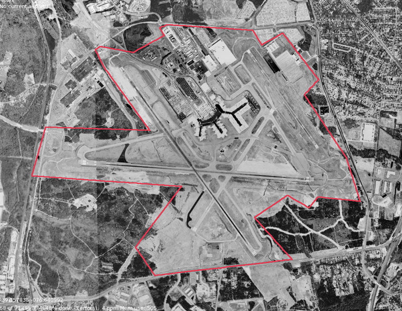
Figure 14: An example of determining an boundary
To draw an airport boundary, select the boundary tool and click at each corner around the airport. This is the area that will be flattened in X‑Plane and filled with airport grass the next time global scenery is cut. The boundary has no impact on the way your scenery is shown in X-Plane–it is only used when submitted to the Gateway and only for a future version of X‑Plane. When drawing the outline, be sure to go in one direction—either all clockwise or all counter-clockwise. When you have placed the last corner, press the Enter key to commit the points to the boundary. At this point, the boundary will appear in the object hierarchy pane; you can then name it there.
If your points aren’t in the places you would like, you can use the vertex tool to click the points and drag them.
For the purpose of this tutorial, we will assume the objects to be used are already created and saved as single object .obj files, or composed into .agp scene files that may contain several objects, trees, facades, and even draped textures. X-Plane’s built-in library contains a great variety of objects. Note that scenery that uses third party resources (such as OpenSceneryX) cannot be uploaded or shared on the Airport Scenery Gateway.
To add an object to your scenery, first find it in the library browser (the pane on the right side of the screen). Selecting an object there will also select the Object tool from the toolbar. Having selected the object, click in the map pane wherever the object should go, or click and drag your mouse around to both place the object and set its heading. If you want to change the object’s heading after placing it, use the vertex tool, and if you want to move the object itself, use the marquee tool to drag it around.
For each object, you can choose at what object density (set in X-Plane’s rendering options) that object will be visible. In the object’s “show with” field (visible in the attributes pane), you can choose to always have X‑Plane draw the object (by selecting “default”) or have X‑Plane only draw the object at the highest level of object density (by selecting “too many”), or somewhere in between.
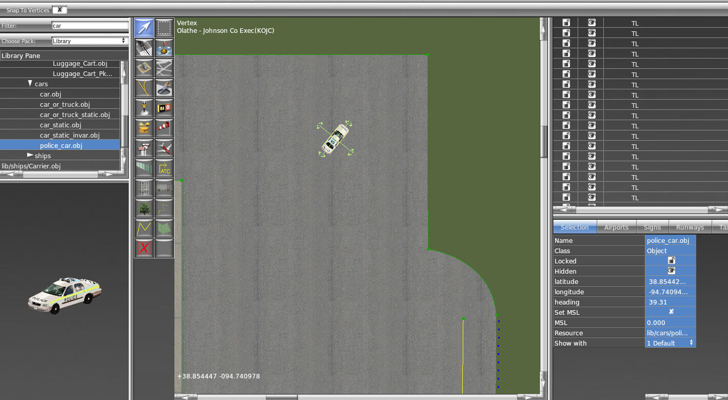
Figure 15: Adding an object to a scenery package
Note that in many cases, your drawn objects don’t have to match the objects in the orthophoto, due to the fact that X‑Plane will draw concrete pads where they would be in real life, and these pads will go on top of the orthophoto.
Object strings and line markings are drawn by default as open Bezier paths. To draw one, select the resource you would like to draw from the library pane (possibly by typing str or lin in the library pane’s Filter box), then, click in the map pane to place each vertex of the line. To change a string or line into a closed Bezier path (a ring), select the string in the hierarchy pane and check the box labeled “closed.”
The .lin files that come as part of the default library are identical in appearance to “Airport Line Markings”, but differ in the way they are stored in scenery files.
Airport Line Markings are intended for aircraft movement assistance, such as taxiway center or edge lines, runway hold markings, etc. They can have lights associated with them and they are written into the apt.dat file. They will not however, align exactly with polygon shapes. They also take up 5 to 7 times as much space in scenery files and end up in a global database: all airport line markings at all airports have to be parsed by the simulator every time X‑Plane starts.
Multi-purpose lines ( .lin ), on the other hand, render faster and therefore should be used in the majority of cases. They will align exactly with a polygon and are subject to the same compression when saved to the .dsf file.
To add a draped polygon (a surface that covers the X‑Plane terrain and takes its shape) to your scenery, first either select the polygon tool or find the resource you would like to use in the library pane (perhaps by typing pol in the library pane’s Filter). Then, click in the map pane to draw the polygon as a Bezier path.
A facade in WED is essentially an image wrapped around a polygon at a specified height. This is used to build a simple building or fence quickly and easily. Users specify only the shape of the structure at its base, its height, and the .fac file to use.
To draw a facade, select the facade tool from the toolbar (or select a .fac file from the library browser), and set the height of the structure in the tool defaults setting pane if desired. Depending on what type of .fac file is used, the tool will automatically draw open or closed Bezier paths for fences or buildings, respectively.
Use the facade tool to trace the outline of the scenery element you would like to draw. You can modify the points later using the vertex tool—remember that holding Alt and clicking on a point with the vertex tool will change it to a point of curvature in the Bezier path. After the facade is outlined, give it a name and change its height in the attribute pane as needed.
Overlay scenery created in WorldEditor can specify forested regions with a high degree of specificity. Using the forest tool, you can draw the outline of the forested region (using only plain nodes, with straight line segments). Before or after a forest is drawn (by using the tool defaults or attributes panes, respectively), you can set the following properties for it:
The default library has a number of forests types under the lib/g8/ path available. These carry names that specify the type and climate zone a given flora type will used for by the autogen system. Matching this climate zone to the location where a your scenery is located (using a _cld_wet option at an airport in Alaska, or _vhot_dry in the Sahara, for example) will ensure the forests match with the autogenerated scenery all around the airport and provide a more consistent overall appearance.
An airport traffic flow defines a particular configuration of runways. Most large airports will have several “flows” depending on weather or time conditions, or type of aircraft, so WED allows you to create more than one flow as well.
An ATC traffic flow starts with an ATC flow item, which defines the flow’s name, its visibility/ceiling requirements, and its pattern runway. It can also specify the following rules:
The last of all flows specified should never include any wind, time or visibility rules. This is the fallback flow if no other matching flow’s rules meet the actual wind or weather conditions. (Note there is currently no option to force an airport to be closed due to the wind or weather rules preventing operation of any runway.) If there is a certain weather scenario not covered by any specified flow and its rules, X‑Plane will always choose the last flow specified, whether that makes realistic sense or not.
To create a traffic flow, select your airport in the hierarchy pane, open the Airport menu, and click Create Airport Flow. Then, after selecting that flow in the hierarchy pane, open the Airport menu again and select Create Runway Use Rule, Create Runway Time Rule, or Create Runway Wind Rule. These rules specify under what conditions the runway should be used. X‑Plane will try to use the rules in order (from top to bottom), so be sure to order multiple flows from most specific to least. It also a good idea to have a generic, catch-all flow that can be used in all conditions in case the condition-specific flows overlook a possible scenario.
Note that the taxi routes (detailed below) generated by X-Plane’s artificial intelligence are not part of the flow—-these routes do not change with flow.
For a step-by-step walkthrough of creating traffic flows, see the four part video tutorial on the X‑Plane YouTube channel. See the article “ATC Flow Authoring in WED” for more information on how to set each field of the ATC flow.
Taxi networks provide guidelines on how to get from one part of an airport to another. If the airport does not have a hand-drawn route, X‑Plane auto-generates a taxi network when it starts. These networks tend to have problems and are not very precise. Specifying a taxi network in WorldEditor will keep the AI-controlled aircraft moving in a reasonable manner around an airport, instead of going through buildings or off the pavement. They also contain important data such as taxiway names and hold short information.
To create taxiway routings for the AI aircraft, use the taxi routes tool and click to trace the path the aircraft should take. To do this efficiently, you may want to preset the properties of the taxi route tool using the tool defaults bar at the top of the window; then, you can draw all departure paths together, all paths for a specific runway together, and so on. If you do not set the properties that way, or need to change them later, you can select the taxiway(s) in the hierarchy pane, and then make your changes in the attributes pane below it. (Note that there are additional fields in the attributes pane, such as latitude and longitude, that should not be edited.)
Picking a runway in the Departure and Arrival fields indicates the segment is in a hot zone for that runway. Setting the ILS field indicates that segment is in an ILS precision area. The Size field determines the largest AI aircraft that is legally allowed to use the taxi route. This prevents aircraft with large wingspans from taxiing along routes that have limited clearance. Most taxiways should be specified large enough for the largest aircraft that could use a given airport–which should match the size of the largest ramp start specified at that airport. The slop field indicates how close your point must be to another taxiway section in order to snap to it. Larger numbers allow the paths to snap together from farther away. The other preset fields are self-explanatory.
When viewed in the ATC Taxi + Flow tab, taxi routes are color-coded for better visualization in the map pane. Runway segments are blue (or purple), basic route segments are yellow, hot zones are red, and ILS precision areas are orange.
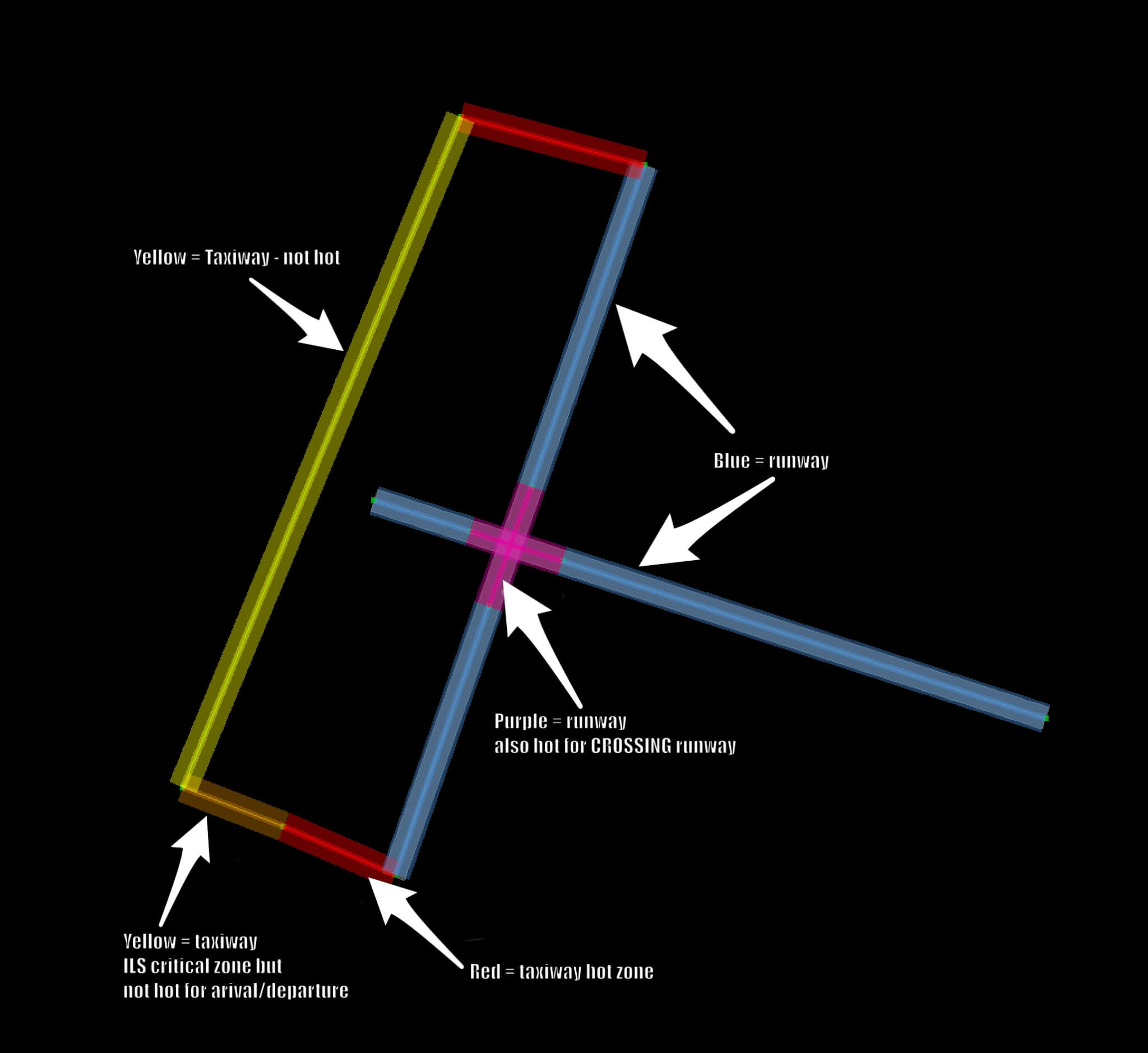
Figure 16: Color coding of ATC taxi route segments
In addition, changing the Size field will change the width of the band. This is to help visualize how much space will be taken up by the largest aircraft of that category. Be sure to provide plenty of clearance–if any part of the band is overlapping, there will not be enough space there for the plane to pass safely in X-Plane.
WED includes a lot of validation to help catch any errors with your taxi networks because they are very complicated systems to design, but also very important. They’re the only way ATC understands how to direct AI aircraft around the airport. Keep the taxi network limited to the preferred and safe routes that aircraft would take at any airport. The ATC will not be able to distinguish rarely or never used taxi routes from the preferred one. Instead, it will always take the shortest and straightest path from a runway to the assigned parking position and vice versa.
See the article “ATC Taxi Route Authoring” for an in-depth guide to designing correct taxi routes. A five part video tutorial is also available on the X‑Plane Official YouTube channel.
Scenery artists can customize routes for airport service vehicles to use in X‑Plane. Ground traffic vehicles are AI-controlled, and each vehicle spends most of its time at specific “parking locations.” When called to duty it heads to either an aircraft’s location or a “truck destination.” Service vehicles will randomly visit “truck destinations” in order to create more traffic and activity at airports. All service vehicles return to “parking locations” after they complete their service.
The three tools used in creating service vehicle networks are:
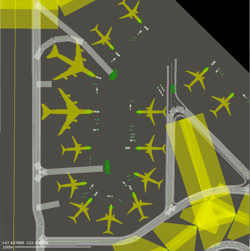
Figure 17: Example of truck routes, parking spots and destinations at KSEA, as seen in the ATC Taxi + Flow tab view.
The available types of service vehicles are:
Note that, in order for an aircraft to receive service, ports must have been specified in Plane Maker.
To begin laying down service vehicle networks, first select the Truck Parking tool and click in the map pane to place locations where the service vehicles will park when not in use. Only one type of vehicle is allowed per spot, which is determined by the drop down. Place parking locations near aircraft when possible so the vehicles do not have to drive a long way. Service vehicles will avoid collisions with other service vehicles and the aircraft they are servicing, but not other objects. (The awareness to avoid buildings and other objects may be available in the future.) If service vehicles need to cover a long distance however, they will use ground truck taxi routes when available.
Drawing the ground truck routes works exactly like drawing ATC taxi routes. Select the ATC Taxi Routes tool and pick “Ground Trucks” from the “Allowed Vehicles” field in the tool bar, then click in the map pane to place the points which outline a route. Service vehicle routes ignore the settings in the Runway, Departure, Arrival, ILS, Size and Name fields, but can be marked one way.
Unlike ATC taxi routes, service vehicle routes can be multiple separate, unconnected networks. Service vehicle routes are not allowed to cross or be too close to any runway, so stand-alone networks separated by runways may be necessary at many airports. Ground routes may be placed through terminal buildings if, in real life, there are paths through the area that X‑Plane is currently incapable of modeling.
Service vehicles are good at maneuvering near their docking locations and need room to do so. This means service vehicle routes should not be drawn close to ramp starts. Leave room around the ramp starts, especially the right side, to allow for this.
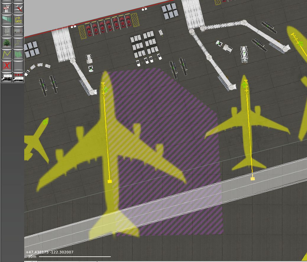
Figure 18: Space for the service vehicles to maneuver around the right (starboard) side of aircraft is indicated by the purple striped area.
The truck destination tool is used to place a location that will randomly call the specified service vehicles. Pick all the types of vehicles that will be allowed to use it in the drop down of the toolbar, then click in the map pane to place the destinations. Vehicles will drive to the spot and park there briefly in order to create more traffic activity at the airport.
X-Plane 12 has built in support for jetways that move and dock with the user’s aircraft. Sceneries require new data to specify where those are. In most cases the upgrade is as easy as opening the existing X‑Plane 11 scenery in WED 2.5 or newer, changing the “Target X‑Plane Version” to X‑Plane 12.00, and exporting the scenery again.
Animated jetways are shown with a red arc that indicates the area where an aircraft’s door must be located for the jetway to be able to dock with it.
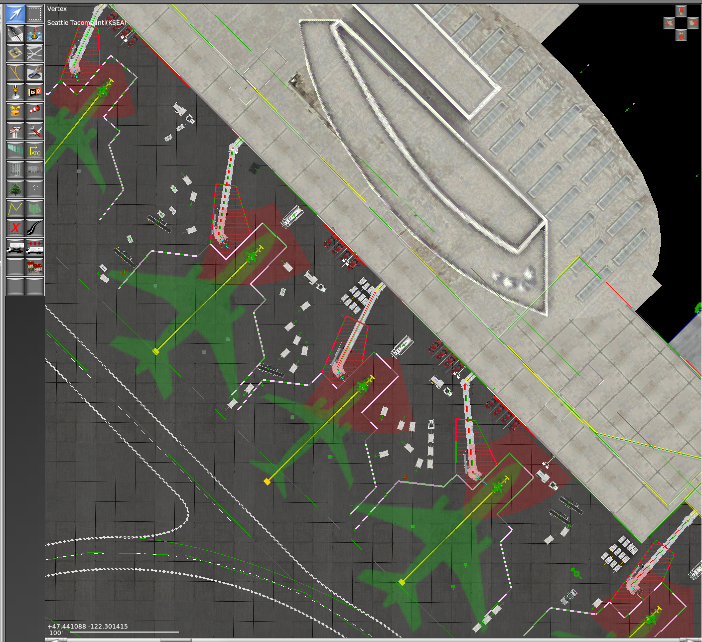
Figure 18: The jetway's movement arc
When drawing new jetways from scratch, WED knows to set the correct wall types to form a proper jetway. When the jetway is drawn starting from the aircraft side, the cabin, tunnel and any more extensions are all preset as needed. In order to get facades to turn into auto-docking jetways there must be a cabin and a tunnel chosen, in that order, on the right end. Watch for the red arc to confirm your jetway will become auto docking.
When you have finished customizing the airport, open the File menu and select Validate. This command will check the WED file for errors based on the current export target. You can change the export target by selecting Target X‑Plane Version from under the File menu. The Scenery Gateway validation target is a much more stringent validation process. This is intended to make sure the scenery is useable with low end or older computers, and to ensure no 3rd party add on libraries are required. Remember that selecting an older version will disable newer features, such as moving jetways, which do not exist in versions prior to X‑Plane 12.00.
If there any scenery errors when you validate or export your scenery, WED will show you a window of all issues, which can range from warnings to major errors that prevent an export. Clicking on one of the lines in this pop up box will allow you to go directly to that issue, or you may select multiple issues at once to fix them all in one action. A “validation_report.txt” file will also be placed in the scenery folder. Use either of these resources to correct the errors before completing the export.
If no errors are present, select Export Scenery Pack from the File menu. If orthophotos were used, the .dsf and .pol file will be automatically created and placed in the scenery folder. The new scenery will be visible the next time you load the area in X-Plane.
All the files that the scenery package depends on are should be its folder (or referenced in the X‑Plane library). To share the scenery pack with a friend (or with the world via the Internet), just zip up your package folder (located in X-Plane’s Custom Scenery folder). Instruct the other user(s) to unzip the folder into their Custom Scenery folder, after which the scenery will appear in X‑Plane on their computer as it does on yours. Beware, however, that external resources will not appear for other users unless they have those same resources installed. Thus, if you use a third party product such as OpenSceneryX in your scenery, be sure to tell your users to install it as well.
You also have the option to upload your files directly to the Airport Scenery Gateway. This is a community-driven effort to collect airport data into a global airport database and will be a collection of all airport layouts authored by the X‑Plane community over the years. Future releases of X‑Plane will periodically share Gateway submissions with all X‑Plane users.
Note: Scenery elements or library items from 3rd party addons such as OpenSceneryX, or any draped orthophotos, are not compatible with the Airport Scenery Gateway.
To upload a scenery package to the Gateway:
To track your airport’s progress on the Gateway:
For more information, to register as an artist, or to download existing files, check out the Airport Scenery Gateway website.
Tools used in WorldEditor can be categorized as follows:
When working with WED, you will be doing lots of selecting. There are two tools used for selecting entities: the vertex and marquee tools. Both of these tools can select entities by two means:
Selecting things with the marquee tool will result in a bounding box onscreen, which can then be manipulated (i.e., scaled), moved, and rotated using modifier keys in combination with cursor movements. For instance, holding down the Alt/Option key with some items selected with the marquee tool will allow you to scale and rotate the object. Selecting things with the vertex tool will allow you to edit entities on a point level—that is, you can move vertices and bezier handles.
There is some overlap in these tools depending on what you are selecting and what you want to do. For instance, you can use the vertex tool to select one end of a runway and move it, but you may also select that same end of a runway using the marquee tool. In a similar manner, you can select a single vertex of a taxiway with the marquee tool and move it, but not edit its shape via bezier handles (for that, you would have to use the vertex tool). A good rule of thumb is that you use the marquee tool to move, rotate, and scale selected items, and you use the vertex tool to manipulate individual points and entities.
Holding modifier keys change the way selection operates in the following ways when using the vertex tool:
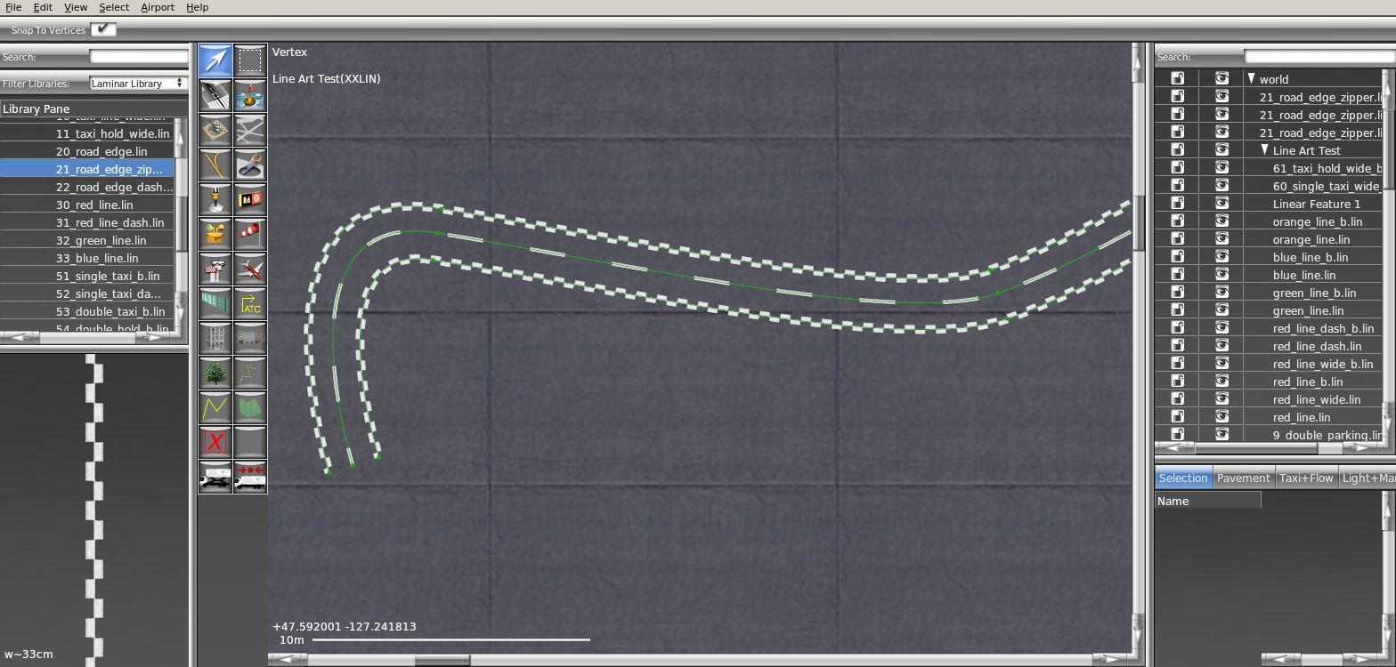
Figure 19: Using Modifier keys to duplicate lines
When using the marquee tool, holding modifier key(s) does the following:
With the exception of the selection tools, all tools in WED are used to create objects from points, lines, and bezier paths. With this in mind, we will consider the tools by type.
Directional point tools include the following:
A directional point tool will allow you to place an entity and set its direction by clicking and dragging when placing the entity. If a single click with no dragging is used to place a directional entity, the entity will be placed with a heading of 0.00 degrees. The heading can be changed by either
Note that the helipad tool is not a “pure” point tool, as helipads can be resized and stretched. However, stretching a helipad to a non-square shape is not recommended, as it will result in a distorted texture in X-Plane.
Non-directional point tools include the following:
Non-directional entities are simply placed by clicking in the map window where you want the entity to be. Each type of entity has its own set of unique attributes viewable and modifiable in the attributes pane.
Linear tools include the following:
A linear tool is defined by two endpoints, though the scenery entities created may later be scaled and rotated as though they were defined as a box. Placement of runways and sealanes can be accomplished with either
If you click and drag for the first point of a runway or sealane, a little crosshair cursor will appear which can then move around for exact placement of the first point. Releasing the mouse button will then allow you to click for the second point as usual.
Exclusion zones are drawn somewhat differently: simply click once and drag to the opposite corner in order to draw an exclusion “box.” Use the vertex or marquee tools to fine-tune the size of this box.
You cannot click and drag with the taxi routes tool; you must click to place the first point, then click again each time to place the next segment. Press enter when the line is complete to stop adding points. To approximate curves with this tool, use multiple short segments. AI aircraft will automatically smooth any sharp angles or crudely drawn taxi routes in the simulator. Similar to the Bezier path tools described below, a new point can be added to a taxi route by selecting the vertex tool, then Alt (Option on a Mac) clicking on the path.
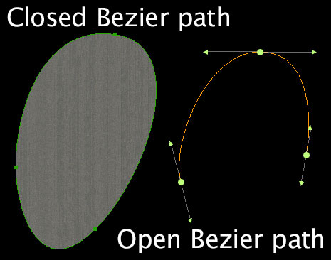
Figure 20: Open and closed bezier paths
Bezier path tools include the following:
Bezier tools are used to create freeform shapes. These shapes are commonly called Bezier curves or Bezier paths.
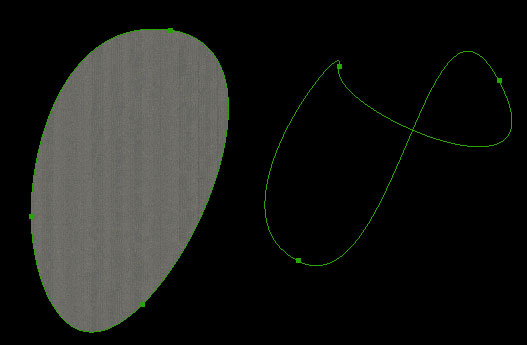
Figure 21: A normal Bezier path (filled, on the left) compared to a Bezier path crossing over itself (unfilled, on the right)
Drawing Bezier shapes may seem a bit foreign for the uninitiated, but with practice, it can become second-nature. There are some important concepts to know in order to successfully work with Bezier shapes. The first is that a Bezier shape may be open or closed. Figure 20 shows an example of open and closed Bezier paths. In WED, open Bezier paths are used only for the taxiline, taxi route, line, and string tools. Closed Bezier paths are used for the taxiway, hole, boundary, facade, forest, and polygon tools.
A closed bezier path is also called a “ring.” It is important to note that a closed Bezier path may not cross over on itself. Figure 21 shows two closed Bezier paths. You’ll notice that the path that crosses over itself has no fill (it is not solid), indicating a problem that will cause the entity not to render in X-Plane.
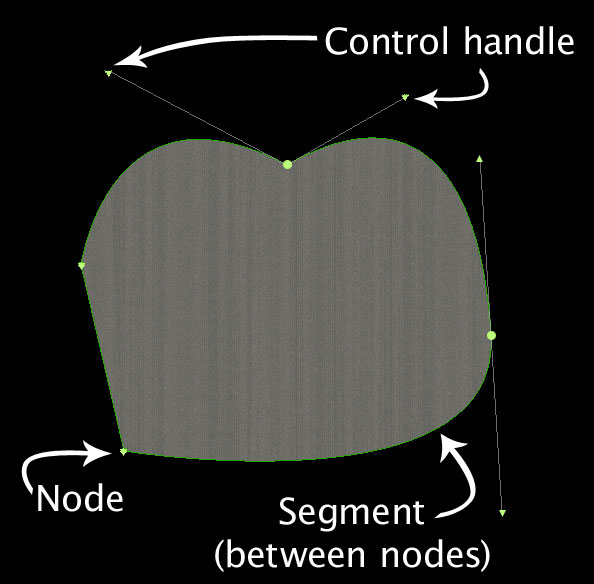
Figure 22: A node, segment, and control handles illustrated in a Bezier path
In order to learn to work with Bezier path, you need to know the pieces that make up a Bezier path. Figure 22 shows the primary parts of a Bezier path. The most fundamental part of the path is the node, represended as a round dot or triangle, depending on the node’s type. Attached to nodes are control handles, which are small triangles at the end of a line. A node can have 0, 1, or 2 control handles. The path between two nodes is called a segment. The location of two connected nodes' control handles determines the shape of the segment between them. For instance, two nodes that each have no control handles will have a straight segment between them. All segments together compost the bezier path.
A node can have a few different configurations, as follows:
With the knowledge of the four node types, the next step is to string those nodes and control handles together in such a way as to create the shapes you want. A bezier path is created by selecting a Bezier tool clicking to outline your shape; a node will be added for each click (or click-and-drag) operation. A Bezier path may have as many nodes as needed to create the shape.
There are two ways to “complete” a shape (i.e., tell WED you are finished adding nodes)—either double-click when creating the final node, or change to another tool, in which case the last node you added will be the last point. Once the shape has been completed, you can edit it with the vertex tool.
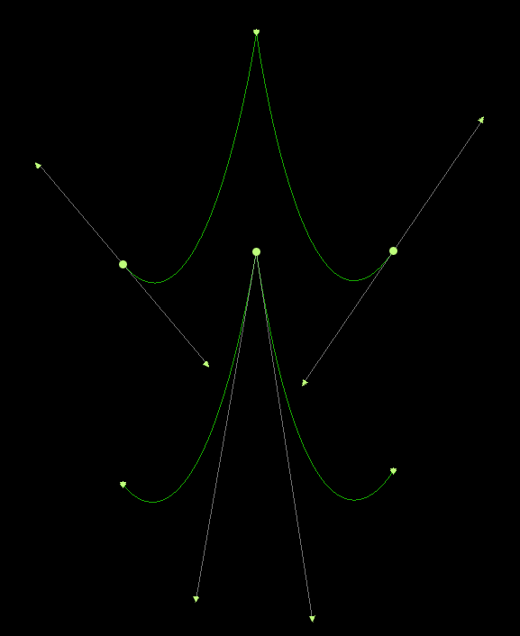
Figure 23: Different configurations of Bezier nodes resulting in the same shape
It is very common when drawing Bezier paths to work with all the node types. There is no one particular way to draw a path. Figure 23 illustrates that two similar shapes can be drawn with completely different types of nodes. With a little practice, you’ll soon get the feel for how you want to create your shapes.
When drawing curves, it is extremely common to convert between node types while in the middle of drawing a path. When in the process of drawing a path, you may only create plain nodes (by single-clicking) or normal nodes (by clicking and dragging). You must place either of these two types of nodes first, (optionally) convert them to a different node type, then continue drawing the path. Note that you cannot convert a node to a single-handle node while in the process of drawing the path. Once the path has been completed, however, you may convert between all types.
To convert from one type of node to another, use the modifier keys Shift, Ctrl (Command on Macs), and Alt keys in combination with single clicking or clicking and dragging. [Figure 2473 lists the keystroke combinations to convert between the node types.
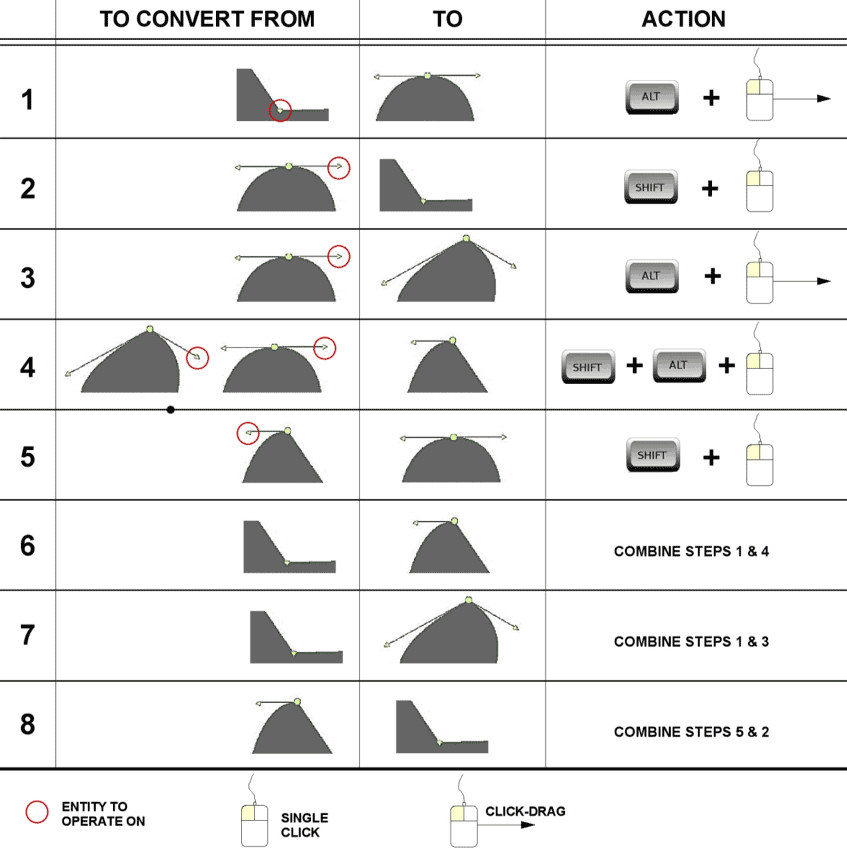
Figure 24: Chart for converting between Bezier node types in WED
Once a closed Bezier path has been drawn, you may want to add new nodes to the existing shape. To do this, use the vertex tool and select the two nodes on either side of the point where you would like to add a node. With the two nodes selected, open the Edit menu and click Split, or press Ctrl+E on Windows or Command+E on Macs. A new node will be created in the middle of the selected nodes.
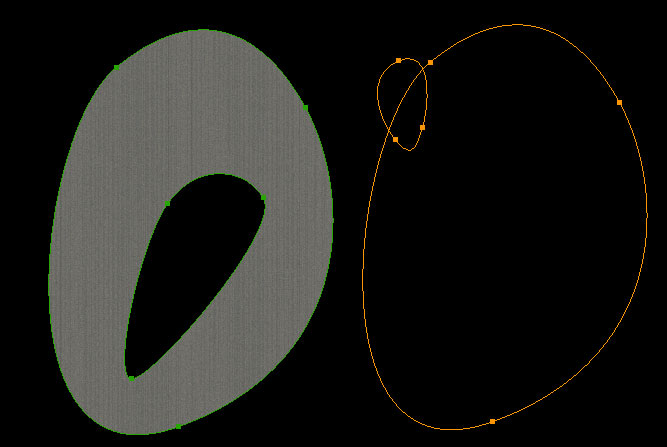
Figure 25: A comparison of a properly drawn hole (which is contained entirely within its parent shape) and an improperly drawn one (which crosses the boundary of its parent shape)
The hole tool is a Bezier type tool and is used to create holes inside of existing Bezier shapes. The most important thing to keep in mind when using the hole tool is that the Bezier hole must be entirely contained within its parent shape. Figure 25 show an example of this, where moving the hole outside of its parent entity will cause the shapes to lose their fill texture. A hole must be associated with another shape—this is done by selecting the parent shape (e.g., by using the marquee tool) before using the hole tool. You may select a shape using either the vertex tool or marquee tool. When the shape is outlined in orange, you may use the hole tool.
Since the hole is attached to a parent shape, moving the parent shape will move the hole also. However, you may select the hole with the marquee tool and move it withing its parent shape to relocate it, or select it with the vertex tool to reshape the hole.
After having created a shape, you can manipulate it: you can stretch it, scale it, or, in some cases, rotate it. To do so, use the marquee tool and select the entity. When you do so, a bounding box appears around the entity. By clicking and dragging one of the box’s nodes, you can stretch the shape. By holding down the Alt key, you can cause the bounding box’s nodes to become rotation nodes; by clicking and dragging a node, you can rotate the shape.
Once a shape is created, in some cases, such as with shapes made with the taxiway or polygon tool, you can specify what kind of surface the it has. The shape’s texture has two properties: type and direction. The type of texture is specified in the attributes pane using the pull-down menu for the Surface property, or by choosing a library file in the Resource field. Typical surfaces are asphalt, grass, dirt, water, and so on. The texture’s heading can be set using the Heading field in the attributes pane. Or, to adjust the texture heading graphically, select the shape using the vertex tool, then hold down the Shift key and click and drag within the shape. As you drag the mouse, the texture will update in real time and you can align the texture as you like.
In order to work with data from another program, you should do a one-time import of the files from that program, then work in WED only until you export your file for use in X‑Plane. You can export the scenery (by opening the File menu and clicking Export Scenery Pack) as many times as you like, but you must re-import files from other programs any time you modify them, such as any time you modify an image file in an image editing program. Note that WED will not monitor your files for duplicates, so you might unintentionally import a copy of a file you already have (such as a DSF).
There is one important disadvantage of repeated import/export cycles: the DSF file format is a highly compressed data format so scenery elements' coordinates will lose precision with every export. Other WED-specific information such as groups or names names given to specific entities are not stored in DSF files at all, so this information is permanently lost. This are some of the reasons we strongly recommend always using the option to import airports directly from the Scenery Gateway–this is equivalent of receiving the full precision and information stored in WED’s proprietary earth.wed.xml files
Note also that WorldEditor will not automatically import projects from older versions. You can, however, import your project manually. Simply point WED’s opening screen to the appropriate X‑Plane folder and choose the applicable scenery pack from the Custom Scenery folder.
The X‑Plane scenery system uses globally unique identifiers called Airport IDs to identify every individual airport. These are also used to determine if any airport in Custom Scenery should remove, or “exclude,” the corresponding airport included in default scenery or otherwise installed. These identifiers are separate from, and in many cases different than, the more commonly known ICAO codes. To make this mechanism work, every airport must use the same Airport ID as X‑Plane uses for its own airport in the same place. Set the WED property “Airport ID” in the airport’s properties according to the section “Creating an Airport From Scratch.”
Some older sceneries may use different Airport IDs. To find the correct, current Airport ID, look up the airport on the Airport Scenery Gateway or Toggle NAVAIDS from under the View menu.
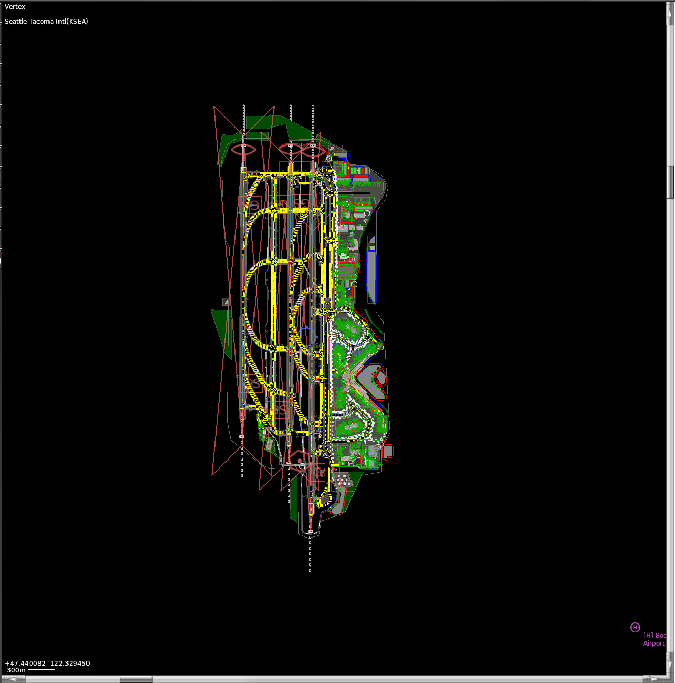
Figure 26: The NAVAID overlay layer showing scenery and nearby air- and heliport.
This layer will show VFR-map-style all airports, heliports and seaports in the default X‑Plane database along with the officially assigned Airport ID for each.
If you have performance issues with WED, you can turn off the visual preview of objects. To do so, open the View menu and click Toggle Preview. Initial scenery load time is increased notably by the NAVAID layer, which can also be toggled off in the view menu.
In the event that WED crashes, users can easily recover their work from a back up file that is automatically generated after every save. First, in the Custom Scenery folder, naviagate to the folder for the scenery that caused the crash. Inside the folder will be two .xml files: “earth.wed.bak.xml” and “earth.wed.xml.” Delete the file “earth.wed.xml,” then rename the other file to “earth.wed.xml.” Upon restart, the scenery file will be restored to the last saved version from before the crash.
As a general rule of thumb, the first thing you should do after encountering any problems is update to the latest version. If you are running the latest version and still have problems, you can check for problem files by manually running the installer found on the X‑Plane website. Select “Update X-Plane,” pick which copy you’d like to update and click the “continue” button. The installer will scan your installation to see if any of the default files are missing or altered, and allow you to restore them.
For additional help, first search for a solution on the X-Plane Q & A site. You can also ask your question on the site if it has not been covered already. Questions are answered by Laminar Research team members and knowledgeable community members. The site also feature commenting, voting, notifications, points and rankings.
When sending a bug report, please include as much information as possible—-anything that the X‑Plane development crew might need to know in order to reproduce the malfunction. This includes (but is not limited to) the following information:
Additionally, before filing a bug report, please:
To file a bug report, please visit the Airport Scenery Gateway and create a free account. WED bugs should be filed on the “Scenery Tools” tab on the Report A Problem page. All bugs are public and ongoing progress or comments can be tracked on this page.
| Menu item | Description |
|---|---|
| New Package | Creates a new package in the package list |
| Open Package | Opens the selected package for editing |
| Change X-System Folder | Changes which X-System folder WED is editing |
| Close | Closes the current scenery pack |
| Save | Saves the current sessions |
| Revert to Saved | Reloads the package from disk, going back to the last saved version. Note that you can undo a revert-to-saved by using the “undo” function under the Edit menu. |
| Validate | Checks a scenery pack for errors and problems. |
| Target X‑Plane Version | Sets the oldest version of X‑Plane that can use the scenery pack. Note: setting this to older versions may not allow newer WED features to export. |
| Import from Airport Scenery Gateway | Imports an apt.dat file, as described above, from the Airport Scenery Gateway database instead of the local disk. |
| Import Roads (+Autogen) | |
| Import Orthophoto | Imports selected file from disk. Note building a scenery pack will turn this file into orthophoto scenery. |
| Export Scenery Pack | Exports the entire scenery pack, DSFs and apt.dat s into your scenery pack, so you can fly it in X‑Plane. |
| Export to Airport Scenery Gateway | Automatically exports and uploads the selected scenery pack to the Gateway |
| Exit (Windows/Linux only) | Quits WED. |
| Advanced | Includes: |
| Import apt.dat | Imports an apt.dat file. This brings up a list of airports in the apt.dat file to select from. Note that the default apt.dat is located in X-Plane 10/Resources/default scenery/default apt dat/Earth nav data/ . You will have the option of only importing some of the airports contained in the file. Hold Ctrl and click (Command+click on Macs) to select multiple airports, then hit the Import button. |
| Import DSF | Imports a DSF file from disk. |
| Export apt.dat | Exports only apt.dat data into a single apt.dat file. |
| Menu item | Description |
|---|---|
| Undo, Redo | WED supports multiple levels of undo/redo for map items. Undo/redo is not available for text editing; instead, simply finish the text edit and then undo. |
| Cut, Copy, Paste Text | Only available for text editing. |
| Clear | Deletes the selection |
| Duplicate | Duplicates the selection. Note that this works for hierarchy items, so you can duplicate whole groups of items in the hierarchy pane. Includes sub options to duplicate in place or to duplicate & move to the current airport. |
| Group, Ungroup | These group the selection in the hierarchy pane, or break apart any group that is selected. |
| Split | Introduces split points into any side of a polygon or line whose end-points are selected. |
| Align | Align nodes into a straight line. |
| Match Bezier handles | Automatically match a line or polygon to the shape of another one. |
| Othogonalize | Straightens all sides of a polygon to make exact rectangles, etc. |
| Make Regular Poly | Makes polygons into rotationally or axially symmetrical shapes. |
| Merge | Merges two selected ATC network nodes into a single node, connecting the incoming routes of both. |
| Reverse | Reverses the winding direction of a polygon. Note that if a polygon is right-side out and is reversed, it will be inside-out and stop rendering. |
| Rotate | Rotates the order of sides on a polygon, which can change the position of facade sides and markings. |
| Crop Unselected | Deletes every unselected element from the WED project. Parents and children of the selected elements in the hierarchy are kept. |
| Convert to | Convert taxiways, draped polygons, airport line markings or lines into another type of entity of this list. |
| Move First, Move Up, Move Down, Move Last | Change the ordering of the selected object in the hierarchy pane (e.g., selecting move first will cause the selected element to be highest in whatever group it is in). |
| Break Apart APG’s | Break apart .agp groups into individual objects, if all .obj referenced are public. |
| Menu item | Description |
|---|---|
| Zoom World | Zooms out to see the entire world. |
| Zoom Package | Zooms to show only the contents of the currently open package. |
| Zoom Selection | Zooms in to see the selected items filling the map pane. |
| Show Line Markings | Shows a simple color preview of taxiway and line markings for apt.dat files. |
| Show Vertices | Shows each vertex as a small dot. |
| Pavement Transparency | Selects a level of transparency for all apt.dat pavement. |
| Object Density | Shows a preview of the objects that a user would see at a given object density (set in the Rendering Options window in X-Plane). |
| Pick Overlay Image | Creates a new overlay image from disk for reference purposes only. |
| Toggle World Map | Turns the low-resolution background world map on or off. When checked, the background map is enabled. |
| Toggle Navaids | Toggles background layer with airport icons and NAVAID locations. |
| Slippy Map | Toggles OpenStreetMap or ESRI map information. |
| Toggle Preview | Toggles semi-realistic preview of objects, AGPs, facades and most other art assets. When checked, these previews are enabled. |
| 3D Preview Window | Toggle the Window, Show Map Area in Preview Window, or Center Map on Preview Camera |
| Restore Frames | Resets the frames of the WED editing window to their default position. |
| Enter Full Screen | Toggle full screen mode on/off |
| Menu item | Description |
|---|---|
| Select All, Select None | Select every object in the package or none of them. |
| Select Parent/Select Children | Select the parent or children of the current selection in the hierarchy. |
| Select Polygon | Given a selected vertex, selects the polygon that contains it. |
| Select Vertices | Given a selected polygon, selects its vertices. |
| Select Connected | Selects disjointed parts of an ATC network. |
| Select Degenerate Edges | Selects ATC edges of zero length (i.e., edges between two points that are on top of one another). These are good edges to delete or the pack will not pass validation. |
| Select Double Nodes | Selects any ATC nodes that overlap each other. These are good nodes to merge or the pack may not pass validation. |
| Select Crossing Edges | Selects ATC edges that cross each other. These edges should be split or the pack may not pass validation. |
| Select Local Objects/Library Objects/Laminar Library Objects/Third Party Library Objects/Missing Objects | Selects objects meeting the criteria |
| Menu item | Description |
|---|---|
| Create Airport | Creates a new airport within the package. |
| Create ATC frequency | Creates a new ATC frequency for the current airport. |
| Create Airport Flow | Creates a new, empty airport flow for the current airport. |
| Create Runway Use | Adds a runway use rule to the selected flow. |
| Create Runway Time Rule | Adds a new time rule limitation to the current flow. |
| Create Runway Wind Rule | Adds a new wind rule limitation to the current flow. |
| Add Metadata | Add metadata fields such as City, Country, etc. |
| Update Metadata | Downloads new, missing metadata (if available) for the airport. |
| Edit Airport [airport] | Changes the current airport to the selected one. |
| Upgrade Ramps | Auto-update pre X‑Plane 10.50 style ramp starts with useful defaults. |
| Upgrade Jetways | Auto-update pre X‑Plane 12 facades or jetways to moving jetways. |
| Age Pavement | Change pre-X-Plane 12 pavement textures to old & worn. |
| Add Pavement Edges | Add cracks & worn look to pavement edges. |
| Mow Grass | Creates lawn mowing tracks around objects. |
| Align Airports | Mass-move airports to bring runways into CIFP compliance. |
| Replace Vehicle Objects | Replace static ground service .objs with X‑Plane 11/12 ground service functions. |
The following is a list of object types with descriptions of the properties associated with them. Note that all objects have an additional Name property, which simply identifies them in the hierarchy, and many have latitude, longitude, or heading fields which are self-explanatory.
| Property name | Description |
|---|---|
| Airport | |
| Type | Seaports and Heliport do not support “Always flatten” |
| Field Elevation | Elevation to use when Airport terrain is flattened at run-time |
| Has ATC | Property specifying ATC availability (X-Plane 9 only) |
| Airport ID | Handle used to idenify and disambuguate airport sceneries. NOT used in user facing displays in X‑Plane 10.45 and later |
| Always Flatten | Flatten terrain completely to elev. specified in Field Elevation |
| Left Hand Driving | Ground Service Vehicles drive on left side of centerline |
| Scenery ID | For Scenery Gateway internal revision control purposes, only. |
| Airport Beacon | |
| Type | The type of beacon at this location. |
| Airport Boundary | |
| Markings | The pavement line markings attached to this boundary, set on a per-point basis. |
| Lights | The lights attached to this boundary, set on a per-point basis. |
| Airport Lines | |
| Lines | The pavement line markings attached to this line, which may be set either at the level of a line or its points. |
| Lights | The airport lights attached to this line, which may be set either at the level of a line or its points. |
| Airport Sign | |
| Name | Interpreted as a sign code for these entities. See the apt.dat 1000 file specification for the meaning of the sign codes. |
| Heading | Specifies the direction the front of the sign faces. |
| Size | Size of the sign, defined as one of several preset sizes. |
| ATC Flow (X-Plane 10 only) | |
| METAR ICAO | The METAR ICAO code of the airport whose weather determines the use of this flow. For smaller airports, their flow may be dictated by a nearer larger airport, so this ICAO may not be the ICAO of the airport that contains the flow! |
| Minimum ceiling | The minimum ceiling in feet/meters at which this flow can be used. |
| Minimum visibility | The minimum visibility in sm at which this flow can be used. |
| Pattern runway | The runway to be used for pattern operations. |
| Pattern direction | Defines whether the airport uses left or right traffic. |
| ATC Frequency | |
| Type | The type of frequency (e.g. ground, delivery, etc.) |
| Frequency | The actual frequency or 8.33kHz channel number, in MHz. |
| ATC Runway Use (X-Plane 10 only) | |
| Runway | The runway to use |
| Departure Frequency | The actual departure frequency, in MHz. |
| Traffic type | A set of aircraft categories (e.g., prop, jet) that can operate on the runway. |
| Operations | The type of operation (e.g. departure, arrival) that can operate on the runway. |
| Legal on-course hdg min/max | This defines the range of headings that the first waypoint for the departure can still be in to receive this runway. |
| ATC assigned heading min/max | Defines the range of headings ATC can give the aircraft on takeoff from this runway. |
| ATC Time Rule (X-Plane 10 only) | |
| Start time | The earliest time this flow can be used, in Greenwich mean time (GMT), or Zulu time. |
| End time | The latest time this flow can be used, in Greenwich mean time (GMT), or Zulu time. |
| ATC Wind Rule (X-Plane 10 only) | |
| METAR ICAO | The ICAO of the airport whose wind is being measured. Like ceilings, the airport whose weather determines flow may not be the same as the airport you are currently working with; small airports must often do what big airports dictate. |
| Direction from/to | Defines the range the wind must come from for the flow to be used. |
| Max speed (knots) | The maximum wind speed for which this rule is in effect. |
| Draped Orthophoto | |
| Resource | The file name of the .pol file that defines the texture for the draped orthophoto |
| Texture Top, Bottom, Left, Right | UV texture bounds used for automatic re-calculation of texture UV coordinates when polygon geometric shape changes. 1,0,0,1 results in the full texture being stretched to cover polygon shape. 0,0,0,0 or Top==Bottom or Left==Right disables automatic coordinate calculation |
| Exclusion Zone | |
| Exclusions | These define what types of 3-D entities are excluded below this rectangle. The OBJ exclusion excludes objects and auto-generated X‑Plane 10 elements. |
| Facade | |
| Height | Height of the facade in X‑Plane |
| Resource | The file name of the .fac file that defines the look of this facade. |
| Pick walls | Check this box to define the wall types on a per-node basis (available in X‑Plane 10 only). |
| Show with | The minimum rendering settings at which this object is guaranteed to appear. By picking higher rendering settings in this popup, you allow X‑Plane to drop your facade when the user’s rendering settings are low. If you pick default, your facade will always appear. |
| Forest Placement | |
| Density | The vegetation density in this forest stand as a ratio, where 0.0 is none and 1.0 is maximum density. |
| Resource | The name of the .for file that defines the look of this forest. |
| Fill mode | Defines whether the forest has trees filling the area, around the edges (linear), or just at corners (points) |
| Helipad | |
| Width/Length | Defines the size and shape of the helipad; square by default. |
| Surface | The appearance of the surface of the pad, such as concrete or asphalt. |
| Markings | Markings on the helipad itself. Only “default” currently available. |
| Shoulder | The type of shoulder around the helipad. |
| Roughness | A ratio of roughness, currently ignored by X‑Plane. |
| Lights | The type of lights around the edge of the pad. |
| Light Fixture | |
| Type | The type of lighting fixture. Non-operational fixtures like apron lights can be placed as library elements. |
| Angle | The glide slope that shows correct descent for PAPIs and VASIs. |
| Line Placement | |
| Resource | The path to the .lin file that defines the look of this line. |
| Closed | When checked, WED will automatically close the line to make a loop. |
| = Airport Line | Virtual property to invoke the Line Style Selector GUI, offering to select a resource that matches the appearance of the choices available for Airport Line Markings |
| Object Placement | |
| Elevation Mode | Select to place the object either at ground level “None”, at an height relative to ground level “set_AGL” or at an absolute elevation “set_MSL”. Set_MSL is available starting with XP10, set_AGL requires XP11.50 or later. |
| Elevation | Height in MSL or AGL as per Elevation Mode property. |
| Resource | The path to the .obj or .agp file that defines the look of this object placement. |
| Show level | The minimum rendering settings at which this object is guaranteed to appear. By picking higher rendering settings in this menu, you allow X‑Plane to not display your object when the user’s rendering settings are low. If you pick “default”, your facade will always appear. |
| Polygon Placement | |
| Heading | The heading, in degrees, to which the draped polygon’s texture is rotated. |
| Resource | The path to the .pol file that defines the look of this draped polygon. |
| Ramp Position | |
| Ramp start type | The type of parking spot (available in X‑Plane 10 only). |
| Equipment | Selects all airplane classes that can legally park at this spot (available in X‑Plane 10 only). |
| Size | Largest size of aircraft to use the position (X-Plane 10.45+ only) |
| Ramp Operation Type | Types of aircraft that park to use the position (X-Plane 10.45+ only) |
| Airlines | List of 3-letter airline codes to specify liveries for parked aircraft (X-Plane 10.45+ only) |
| Runway | |
| Width | Change the default width. |
| Surface | The material the runway itself is built out of. |
| Shoulder | The material the shoulder of the runway is built out of, if there is one. |
| Roughness | A ratio for how bumpy the runway is (currently ignored by X-Plane). |
| Centerline lights | A check box to enable centerline lights on the runway. |
| Edge lights | The type of edge lights. Note that X‑Plane does not vary brightness between MIRL, HIRL and LIRL. |
| Distance signs | Check this box to have X‑Plane generate distance remaining signs every 1000 feet. |
| Displaced threshold (at each end) | The number of meters to displace the landing threshold from the end of the runway. |
| Blast pad (at each end) | The number of meters of blast pad next to the runway. |
| Markings (at each end) | The touch down markings for this end of the runway. |
| Approach lights (at each end) | The type of approach lights for this end of the runway. |
| TDZ lights (at each end) | Check this to enable touch down zone lights on this end of the runway. |
| REIL lights (at each end) | The type of runway end identifier lights—pick unidirectional, omnidirectional, or none. |
| Sealane | |
| Width | Change the default width. |
| Show buoys | Check this to have X‑Plane generate buoys along the sealane. |
| String Placement | |
| Resource | The path to the .str file that defines the look of this object string. |
| Spacing | The distance between object placements in meters. |
| Closed | Check this to make a closed loop rather than an open line. |
| Taxi Route | |
| Split | Cannot (and should not) be changed. |
| One way | Check this if traffic on this route should only flow in one direction. Be careful with this property, as it puts pressure on ATC to make circuitous routes. |
| Size | Maximum size / wingspan of aircraft per ICAO classification allowed to traveling the segment |
| Allowed Vehicles | Type of traffic handled by route: Aircraft or Ground Vehicles |
| Runway | Select which runway the ATC taxi route is on. |
| Departures | A set of all runways that this route intersects with for the purpose of departures. This can include an intersection between the route and the airspace after the departure end of the runway. |
| Arrivals | A set of all runways that this route intersects with for the purpose of arrivals. This can include an intersection of the route with the airspace before the touchdown zone or after the departure end. |
| ILS precision area | A set of all runways whose ILS precision areas intersects this route. |
| Taxiway | |
| Surface | The material that makes up the surface of this taxiway. |
| Roughness | A ratio for how bumpy the runway is (currently ignored by X-Plane). |
| Texture heading | The direction of the “grain” of the surface, in true degrees. |
| Line attributes | The pavement line markings attached to this taxiway—may be set on the entire taxiway or on segments by selecting individual points. |
| Light attributes | The airport lights attached to this taxiway—may be set on the entire taxiway or on its points. |
| Tower Viewpoint | |
| Height | The viewpoint’s height above the ground when using the tower view in X‑Plane. Note that this simply controls where the camera is placed in tower view mode—it does not create a control tower. Place a control tower object using a library object. |
| Windsock | |
| Lit | Check this for the windsock to be lit at night. |
This is a broad overview of the architecture of X-Plane’s scenery system. It provides a road map for authors on how the various components fit together.
In X-Plane, all scenery content comes in a scenery package. A scenery package is a folder with a predefined file organization.
Custom scenery is typically distributed as a single scenery package. A scenery package can contain art assets for the library, tiles, airport data, or any combination of the above.
Scenery packages are installed in the “Custom Scenery” folder. Scenery packages have a priority order, defined by their file name alphabetically; X‑Plane also stores the default “global scenery” in packages (stored in the Global Scenery folder) and the sim’s built-in art assets are stored in packages in Resources/default scenery/ . All third party scenery should be packaged and installed in the “Custom Scenery” folder.
See the “Expanding X-Plane” section of the X‑Plane 10 manual for information on how to download and install a custom scenery package.
A scenery package is simply a folder that contains scenery. Within that package may be many files, including:
X-Plane divides the planet into thousands of 1x1 degree “tiles,” which are “cut” along latitude and longitude lines. For a given area of the earth, tile files are loaded to build the local contents of the planet. There are two kinds of tiles: base mesh and overlay.
X-Plane normally maps a 3x2 tile region (3 east-west, 2 north-south) to provide about 200x200 km of loaded scenery at any one time.
There are two kinds of tile formats: DSF (distribution scenery format) is the current tile format, supported in X‑Plane 8, 9, and 10. ENV (environment file) is the legacy tile format supported in X‑Plane 6 and 7 (and supported but deprecated in versions 8 and 9). The rest of this article will refer only to DSFs. Any new scenery you create should use DSFs.
Tiles are named by the latitude and longitude of their southwest corner. They live in a folder that defines a 10x10 block of tiles, defined by its southwest corner, and that folder in turn lives in a per-planet folder, which lives in your custom scenery package. For example, consider the following hierarchy:
“My Awesome Boston Scenery” is the name of the package. Note that there can be no sub-folders introduced in this particular layout—layout of DSF tiles is fixed.
DSFs are binary files. As such, they contain the coordinate and location data for a tile but not the art assets. For example, in an orthophoto scenery package—that is, scenery where the ground texture is taken from a real photo—the shape of the mesh (the elevations) will be in the DSF, but the image of the orthophoto will be in separate art asset files.
Tile files can contain:
In all cases, the DSF file contains the coordinate location information and a reference to an art asset file that is stored separately.
For any given tile, only one tile file can provide the base mesh, or ground. The base mesh is a textured triangle mesh used to model mountains, water, land, etc. Base mesh tiles can also contain all of the components of overlay files if desired.
For further reading, see the DSF File Specification and DSF Usage by X-Plane articles on the X‑Plane Developer Site.
A tile file can be marked as an overlay—in this case, its contents are superimposed over other tile files. Overlay files cannot contain any base mesh information. An overlay file is often used to add additional details. For example, an overlay tile could add the buildings of an airport.
Overlay tiles are loaded in priority order. An overlay can contain “exclusion zones,” which are lat-lon rectangles that prevent elements of lower-priority tiles from being loaded. For example, if an overlay tile contained placements for custom buildings for Manhattan, the author would also create an exclusion zone around Manhattan that would prevent the default buildings (that ship with X-Plane) from appearing there.
All art assets are stored in scenery packages, but never directly inside a DSF. Typically an art asset is built from a combination of text files and image files. X‑Plane supports DDS, PNG, and BMP; BMP is not recommended. DDS is the preferred format for scenery use. The text files often contain information on how to use the texture and other useful properties. For example, the “.net” file format, which defines a road network, indicates the shape of roads to be built, the physical properties of the roads (e.g., how bumpy they are), how to map the texture to the roads, and where to place cars on those roads.
A quick cheat sheet to art asset file types:
Note that .pol (draped polygons) can be used in an overlay, while .ter (base mesh terrain) can only be used in base meshes. Base mesh performance is significantly faster than draped polygons; draped polygons should only be used to customize small areas of the world, like an airport surface area. These files are not appropriate for large-scale orthophoto scenery!
Art asset “primary” files (e.g. OBJ, FAC, etc) can be in any location within a scenery package—they are defined by relative paths. So you can organize your art assets as desired. The dependent (“secondary”) files like DDS textures should be in the same folder as the art asset. An example:
In this layout, the .obj files can be moved anywhere within My Awesome Boston Scenery as long as the relative paths in the DSF are adjusted.
OBJ files are the main way to get 3-d models into X‑Plane. They are used for both scenery models (e.g. buildings) and the 3-d visualization of airplanes. An OBJ is a text file, but typically they are edited using a 3-d editor like AC3D or Blender and exported. Objects can be animated, and have a number of specialized features that can be used only in airplanes.
For further reading, see the OBJ8 Specification article on the X‑Plane Developer site.
The polygon definitions in a DSF can sometimes have holes and sometimes they can be bezier curves; what is allowed depends on the art asset type. For example, bezier curves are allowed for draped polygons but not facades; holes are allowed for forests but not facades.
For further reading, see the DSF Usage by X-Plane article.
Road networks may be specified in overlay files, but they require MSL elevation (that is, their altitude is predefined). The lack of on-the-fly elevation adjustment for overlay road networks is a problem for making add-on road packs; fixing this limitation is an area of ongoing development.
For further reading, see the .net File Specification article on the X‑Plane Developer site.
The library provides a way to locate art assets by a virtual file system, rather than by the physical file system. The library allows one scenery package to “publish” an art asset (by providing it with a virtual file name in the library) and another scenery pack to use that art asset (by referring to it by its virtual file path).
The library system is useful for a few reasons:
Note that image files are not shared via the library system; instead the text file that references them is shared.
Art assets do not have to be placed into the library system—a package can simply access them by relative file paths. Or, a package can put its art assets into the library and then reference them by virtual path, allowing for customization by other packages.
Art assets are placed in the library by putting a file called “library.txt” into the root of your package, like this:
Note that in this case, another scenery package that references houses/house1.obj will not use these files. That is because scenery packages can only use each other’s art assets via virtual path. A scenery pack that references “lib/g8/buildings/60_30.obj” (a virtual path) might end up with either house1.obj or house2.obj.
Library files let you specify the replacement semantics for art assets–that is, a library file can provide additional variants of an art asset or replace the art asset completely. Libraries can specify what tiles (in latitude/longitude) can use the art asset for ‘regionalization’.
The data that describes the layout of an airport are stored in apt.dat files. There is one apt.dat file per package per planet, like this:
The apt.dat file can contain one or more airports; each one fully replaces the previous airport’s definition. (That is, you cannot simply add a runway to the existing KBOS, you must fully re-specify KBOS).
You do not need to provide tiles for the airports you cover, or vice versa.
Airport data does not affect the terrain type below the airport; airports in the default scenery that X‑Plane ships have grass underneath them because the base mesh creation process added the grass. If you add a new airport, you may need to include an overlay tile with .pol placements that drape new terrain over the old; X-Plane’s art assets for airport grass are all exported into the library for this purpose.
Airport definitions do not use any specific art assets; the file format models airport data and lets X‑Plane use built-in art assets to draw.
However, all of the types of drawing that are possible in an airport (pavement, lines, lights) can be created using DSF overlay data. The intention is for authors who want to truly customize the look of their airport to use DSF overlays.
Some of X-Plane’s art assets for airports are available via the library.
For further reading, see the Advanced Airport Customization article on the X‑Plane Developer Site.
Here are some examples of scenery add-ons:
Since Version 8, X‑Plane has employed a library system to locate the bitmaps, models, and other graphic resources it depends on. You can use the library system to replace virtually any part of the artwork for the global scenery.
Any X‑Plane scenery package can be a library. To be a library, a scenery package must have a text file called library.txt directly inside it. This text file contains a list of all of the resources the library shares with X-Plane.
X-Plane scenery packages can be in either the Custom Scenery folder or the Default Scenery folder. The Custom Scenery folder is for add-on scenery packages that are installed by the user; the Default Scenery folder is for the scenery packages that come from Laminar Research and are installed with the simulator.
Note: The X‑Plane updater/installer will sometimes upgrade the default scenery packages that come with the sim. It will not alter custom scenery packages. For this reason, all add-ons should be placed in the Custom Scenery folder!
The library.txt file maps a file path for a resource inside the package to a virtual path that scenery can use. File paths are the actual locations of the objects on disk. Virtual paths are used by the DSFs that need artwork.
As X‑Plane loads scenery, it must locate each object, terrain definition, etc. First X‑Plane looks in each scenery package, in alphabetical order, first in custom scenery, then in the default scenery folder. If X‑Plane finds a virtual path in a library.txt file in a package, it uses the object or terrain in that package located by the file path that is associated with it.
If X‑Plane cannot find the object as a virtual path in any library, it then looks in the scenery package the DSF is located in for an actual file. A few things to note about this:
You can customize the objects used in the global scenery. The virtual paths for the objects in the global scenery are named by their size and the terrain they are used with. The size can be thought of as a maximum limit as you make objects; this is how much space the scenery-creation tools reserved for each object.
There are two separate sets of objects for the global scenery—one for the US and one for the rest of the world. Because the US has much higher road density, the US objects are all relatively small. World objects are much larger.
The global scenery objects are not meant to be one building each. For example, a 200x30 meter object in the US can be 7 houses next to each other, a shopping mall with a parking lot, or one large building.
You can customize the terrain textures used in X‑Plane. This is done by providing new “terrain info” ( .ter ) files. If you do not provide .ter files, X‑Plane will not use your textures. X‑Plane loads your .ter files and from there will pick a PNG in your package. If you override a .ter file, you must provide all of the textures for that .ter file in your package.
Night lighting is not automatic for scenery; you must provide a TEXTURE_LIT line in your .ter file to enable night lighting. The lit texture may have any name; we recommend using the _LIT suffix for clarity, but any name will work.
Someday X‑Plane may feature seasonal textures; when this happens, the TEXTURE_LIT command will allow one .ter with multiple daytime seasonal textures to share a single night lighting map.
X-Plane uses exactly one road definition (a .net file) for all roads in a given DSF. One .net file may define many road types, so subtypes within the road file are used to create variety. This means you must include all of the textures and objects for your entire set of roads.
All default beaches in X‑Plane exist in one image file and are referenced via one .bch file. So you must provide all beach definitions if you are going to provide any. Only one beach definition (a .bch file) may be used per DSF. Subtypes within the beach are used to create variety.